
Before I purchase these speakers would they be good for the f5 turbo ?
F5T would be fine unless you listen loud in a very large room with those speakers...but if those were your listening habits you probably wouldn't want a standpoint 2 way anyways.
Thanks Sangram. It looks like I got lucky & jfets survived but they didn't really match all that well so I'm going with some sets of BL Toshibas I had that were perfect matches instead. Both sets tested out at 8.65 - 8.67 ma at 12v with a 10R resistor off the drain.
I changed R5 & R6 to 2.2k when I first built the amps. I was using a single jfet pair per channel then with 4 pair output and wasn't able to get enough bias. I never changed them back when I doubled up the jfets. I changed them back to 1k now.
While I'm at it I also added some 100R resistors between the jfet drains and the cascode emiters as recommended by Mr. Pass. Just for peace of mind.")
I'll have to test out P3 when I get it going again. Come to think of it even back when they were a stereo V2 it had the same harshness when it warmed up. I used a new set of mosfets when I split it into monos and used a different set of jfets too, the ones that were in there now. I did reuse the diodes.
Debating changing the thermistor arrangement. I wish I knew why it was done like that.
If I find anything I'll post it.
I changed R5 & R6 to 2.2k when I first built the amps. I was using a single jfet pair per channel then with 4 pair output and wasn't able to get enough bias. I never changed them back when I doubled up the jfets. I changed them back to 1k now.
While I'm at it I also added some 100R resistors between the jfet drains and the cascode emiters as recommended by Mr. Pass. Just for peace of mind.
I'll have to test out P3 when I get it going again. Come to think of it even back when they were a stereo V2 it had the same harshness when it warmed up. I used a new set of mosfets when I split it into monos and used a different set of jfets too, the ones that were in there now. I did reuse the diodes.
Debating changing the thermistor arrangement. I wish I knew why it was done like that.
If I find anything I'll post it.
Last edited:
Pass F5 V2 partial kit on Ebay ??
Mosfet pure class A amplifier thick PCB turbo V2 partial kit !! | eBay
Is someone have experience with this kit ? Would you recommend it?
All transistors are there and boards.
Thinking of making F5 V2 50watts clones.
Thanks
Mosfet pure class A amplifier thick PCB turbo V2 partial kit !! | eBay
Is someone have experience with this kit ? Would you recommend it?
All transistors are there and boards.
Thinking of making F5 V2 50watts clones.
Thanks
50/60Hz hum at output
Hello! May I please specifically adress Kyle and Keremito:
I was reading your discussion about the 60Hz hum you have noticed and obviously removed completely by this 2Ohm/2W resistor. As I have such hum myself as well I would like to try your receipe and want to double check to make sure I got you right:
Are you saying, that you are removing the short between the "G"-pad and the "Link"-pad and you are replacing the wire by a 2Ohm resistor?? Correct??
The hum I have is at both channels and it is about 3.5mVrms both sides.
Would appreciate your confirmation.
Hello. What my amplifier had was a low level noise that did not increase with the input level. It did not have a 60 Hz hum.
Kyle discovered that by placing a 3 ohm, 3 Watt resistor instead of the link in the preamplifier board the noise was removed.
I used a 2 ohm, 2 Watt resistor, it worked.
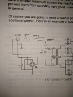
Make sure you audio have implemented the ground isolation circuit with a diode bridge and thermistor as shown in the power supply schematic on the F5 turbo documentation.
Good luck.
Angel
Kyle discovered that by placing a 3 ohm, 3 Watt resistor instead of the link in the preamplifier board the noise was removed.
I used a 2 ohm, 2 Watt resistor, it worked.
Make sure you audio have implemented the ground isolation circuit with a diode bridge and thermistor as shown in the power supply schematic on the F5 turbo documentation.
Good luck.
Angel
I have noticed this in NP's article about the F5T. When I noticed, I had already finished my PS and was too lazy to consider adding it. If the hum persists after trying the HBR, i will have to do this.
The diagram shows two grounds the chassis ground before the AC input and the audio ground (triangular symbol) at the diode bridge and PSU. These should not be together. Where is the audio ground connected to now? Straight to chassis or floating?
I strongly encourage you to do the audio ground isolation. I think I blew the output transistors when I had it disconnected while chasing the noise problem. I connected an input while the amp was on, I heard a telephone conversation or radio intrusion for a fraction on a second before the mosfets exploded.
50/60Hz hum at output
Keremito, I apologize for my ignorance. I simply have not carefully looked at the schematic. Sorry! NOW I see what it is! Indeed, I was wondering about the question if and how I can join chassis ground and system ground. So far I have the system ground "floating" and it works OK except for the slight hum (3.5mV only) which very well might go away with the rectifier/thermistor circuit! I will try this rather than the HBR!! Is the CL60 still the recomended thermistor?? Bit inconvenient to source. Any other recomendation? Guess any 10Ohm/5A NTC will do, right??
Keremito, I apologize for my ignorance. I simply have not carefully looked at the schematic. Sorry! NOW I see what it is! Indeed, I was wondering about the question if and how I can join chassis ground and system ground. So far I have the system ground "floating" and it works OK except for the slight hum (3.5mV only) which very well might go away with the rectifier/thermistor circuit! I will try this rather than the HBR!! Is the CL60 still the recomended thermistor?? Bit inconvenient to source. Any other recomendation? Guess any 10Ohm/5A NTC will do, right??
- Home
- Amplifiers
- Pass Labs
- F5 Turbo Builders Thread