I've used two 19/24V units to power an F5 or two and have had no problems, these were bargain-basement types and the 19V units failed because they were unable to handle 1A constantly, but the 24V were fine.
You can see a minor blip in the DC output when you disconnect one rail of the F5, but the output settles back to 0V very quickly and it does not damage (a decent) speaker. There was an explanation for this somewhere on the thread. I had made a power-on delay for the amp but ended up not using it for either build. Eventually I discarded the SMPS because they ran very hot, hotter than a linear supply. The sound quality did not change much, if at all.
With a single unit and active zero, there will also be a time when the half-supply is coming up (depending on how you build it) and you might end up with strange effects on the output. Best to measure and be sure, at least a few dozen power cycles before you connect your main speakers.
I assume since you have an output cap you are prepared for the massive power-on thump, as the cap charges itself through the speaker. This effect will probably be quite a bit more audible than the power-on delay of a few milliseconds between two power supplies. In my experience this was never an issue, and both effects are completely eliminated by a power-on delay on the speaker line. For the single supply version cap needs to be grounded via a 500 ohm resistor to charge up.
Hi all,
currently planing to order the Jfets for a F5 build, my dealer is running out of 2sj74,
and the best match quad i could get is about 9mA for the IDss.
would this match quad of 2sj74 and 2sk170 of Idss of 9mA suitable for this Amplifier?
thanks in advance for your expertise.
currently planing to order the Jfets for a F5 build, my dealer is running out of 2sj74,
and the best match quad i could get is about 9mA for the IDss.
would this match quad of 2sj74 and 2sk170 of Idss of 9mA suitable for this Amplifier?
thanks in advance for your expertise.
What will be the degradation if the idss is, let say, 6mA which is slightly above the constant current 5mA?
FWIW, I used the 6.5mA Toshiba jfets to build a F5 with 2 pairs of Fairchild output devices per channel. It works perfectly right from the beginning and sounds lovely with my 86db Carver ribbon speakers.
I will love to give my "ordinary Aleph" a "J" companion") I have quite a few 6mA-ish 2SJ74's ready .....
I have quite a few 6mA-ish 2SJ74's ready .....
FWIW, I used the 6.5mA Toshiba jfets to build a F5 with 2 pairs of Fairchild output devices per channel. It works perfectly right from the beginning and sounds lovely with my 86db Carver ribbon speakers.
I will love to give my "ordinary Aleph" a "J" companion
I have quite a few 6mA-ish 2SJ74's ready .....I've seen the instructions from Mr. Pass (and from Zen Mod) to set P1 and P2 to minimum (zero) resistance before initial bias setting, but would like to confirm that some convenient mini-clip points to take these resistance measurements from are:
for P1: measure resistance between physical "top" (end closest to V+ pad) of R7 and "top" of R13 (end attached to "bottom" of R5)
and similarly,
for P2: measure resistance between "top" of R8 (end closest to V- pad) and "top" of R14.
Does this seem right?
In order to get to minimum resistance across each pot, I turned the adjustment knob fully Clockwise on each. (Which made me wonder because I saw a post somewhere in which a diyaudio forum member adjusted his pots fully counterclockwise to begin. I suppose that's the reason why Papa and Zen Mod both referred to measured R, not rotational direction, in their instructions. I hope I got that right.)
I used Bourns PV36P pots, because the adjustment knob on this unit allows easiest adjustment from the "top" of the amp. (Screwdriver oriented vertically, rather than horizontally.
left or right turning of pot - depends how you orient it , so 50% of possibility to make a mistake , thinking in right-left terms
however , if you locate gate resistor for each mosfet , then locate which side of it is pointing to gate , simply put probe on other side of resistor , second probe to adjacent rail and that's it ......turn trimpot to see decreasing resistance .... , then use sharpie and draw nice arrow for proper turning direction , with "-" sign ;
same applies to both mosfets , one is practically sitting on positive , other sitting on negative rail
Zen Mod: after looking at the board again (V3.0 cviller layout on 2013-11-21), and consulting both the original Pass article, and the latest official F5 schematic from Nelson's F5Turbo article, I think we are talking about the same basic test points, provide that the "gate resistors" you refer to are the two 1/4 watt 100 ohm resistors (47 ohm in the original article) that Nelson "placed in series with the gates of the MOSFETS to prevent parasitic oscillations". The resistance between the V+ rail and the physical "top" (viewing the board face on; pads for the big MOSFETS at the bottom edge) of the 1/4 watt R13 should be set to minimum. And the same should be done between the V- rail and the physical "top of R14.
Sorry for the excruciating detail in this post! And thanks again for your help!
Sorry for the excruciating detail in this post! And thanks again for your help!
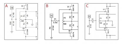
Hallo, I’m very confused. I did not understand what is the best solution for the entry stage for my F5 (A - B -C?).
My intention is to put a preamp before F5.
What is the best solution:
Bride of Zen preamp (with 15db gain)
B1 (only buffer).
My loudspeakers are:
AB2 | PMC Loudspeakers
Many thanks
My intention is to put a preamp before F5.
What is the best solution:
Bride of Zen preamp (with 15db gain)
B1 (only buffer).
My loudspeakers are:
AB2 | PMC Loudspeakers
Many thanks
Attachments
Hallo, I’m very confused. I did not understand what is the best solution for the entry stage for my F5 (A - B -C?).
My intention is to put a preamp before F5.
What is the best solution:
Bride of Zen preamp (with 15db gain)
B1 (only buffer).
My loudspeakers are:
AB2 | PMC Loudspeakers
Many thanks
I believe "A" is the schematic for the boards from the DIYaudio store. If you use those boards, which you probably should, you will have to use "A".
With those speakers you want gain in the preamp. I would say the B1 is not the best choice unless you listen at low volumes only. BA-3 might be a good choice as well, boards available from store.
Lot's of different flavors of preamps on this forum...BOZ uses very high voltage rails which limits your ability to experiment with other preamp designs later.
I have heard those PMC speakers. I like them a lot. It's a very lively speaker though and the F5 is a lively amplifier which may effect your decision on what to build for a preamp.
I would say the B1 is not the best choice unless you listen at low volumes only.
Depends...
If you drive the F5 (15,3dB gain) to output 25Wrms into 8 Ohms you'll need an input voltage of 2,4Vrms.
Most digital sources output between 2 and 3Vrms, 2Vrms being the implicit "standard". This output is at maximum possible output level. Mind you, many manufacturers set up their players with a relative high output level, as "louder is better" in a direct shootout in the shop. People tend to prefer the louder component in a direct A-B comparison. Sales BS that stays with you for the rest of your player's life.
That's why level matching is so important in ABX testing Call it the "loudness war for audio equipment" if you like.
So if your source components are loud enough the B1 could be a healthy choice. Just keep in mind that all amplification that is destroyed by the volume control will give you by-products of gain that you effectively do not need.
My speakers are around 88dB efficiency (Accuton C2-220, C2-79 and C2-12 units) and my B1/F5 combination plays more than loud enough getting it's signal from a Blue Sound Node 2. I have to crank the volume open a lot more than usual (between 12 and 3 o'clock) but that doesn't worry me.
Last edited:
I had the Mezmerize preamp connected to my F5 and I couldn't get enough volume for normal listening when playing a quiet classical CD.
Right now I'm using a Marantz AVR (zone 2 analog) as a preamp and normally have the volume around 8/10 to drive the F5 at good volume. My speakers are rated 90dB efficiency.
Right now I'm using a Marantz AVR (zone 2 analog) as a preamp and normally have the volume around 8/10 to drive the F5 at good volume. My speakers are rated 90dB efficiency.
- Home
- Amplifiers
- Pass Labs
- F5 power amplifier