30W is the maximum allowable dissipation at 125C die temp. Using those two variables with the thermal resistance will yield the minimum possible external resistance for a number of use cases.
It is a specification of limits, not of performance. The designer is left to compute the actual heatsink and thermal material required to not exceed those conditions.
The max continuous drain current at 125ºC (case temp) is a bit north of 4.5A. With 23V rails that's over 100W.
The 30W figure I used was the approximate wattage at the desired 1.2A bias.
(In both cases I ignored the voltage drop over R7/R8.)
Device is derated for temperature, so no, 100W is not possible at 125C in a 150W/25C device.
The vertical MOSFET structure does not have similar SOA limitations as a bipolar but it does have limits and they do need to be observed. From memory you can have a max of 30-40 watt continuous dissipation at 125C. This discrepancy is one of the reasons that vertical MOSFET manufacturers do not either characterise or recommend or even support linear operation of their devices (not that it stops us from using them). This is why you will not find a DC SOA graph in their datasheet, you have to see how much it can take before burning out.
For the record, I have run 25W through a device at 90C case/115 internal and it worked fine. Smelled really bad, but worked just fine. The back of the case did have blisters after so it wasn't usable for long-term applications. I wouldn't risk 125 internal and 100W through the die, it won't do it.
.... This is why you will not find a DC SOA graph in their data sheet....
He he, yeah, I sort of wondered about that.
Cheers,
Jeff.
I was looking for one plotted against temp (as the heading of all those charts says Tc=25º)...
... but I just noticed that the bottom corner of that chart says Tc=25º; Tj=150º. That's one hell of a heatsink.
Anyway, the slope of the DC SOA certainly appears to be 150W, even at Tj=150º (as long as you're getting rid of the heat through the case).
... but I just noticed that the bottom corner of that chart says Tc=25º; Tj=150º. That's one hell of a heatsink.
Anyway, the slope of the DC SOA certainly appears to be 150W, even at Tj=150º (as long as you're getting rid of the heat through the case).
Hmmmm.... I didn't realize this was such a hotly debatable topic.
I'm sure I'm driving it a little out of class A because I do get some additional heat; 6C at most under the hardest use. Most of my experience with MOSFET technology is processor dies and I know those will soldier on just fine for years idling at 72C and seeing sustained temps of 86C on the die measured with a thermal diode. I realize the information I'm looking for is in the spec sheet and I did look at it, but I'm still learning a lot and I'm not sure how to interpret what I'm seeing.
What I'm hearing is when the case temp reaches 79C or so, there is a distinct softening of the top end, presumably because the MOSFET is showing more internal resistance. I like that. It's sounding like folks are having better luck that I am pushing heat to the sink so I may need to reevaluate my thermal interface solution.
When I say case temp I'm meaning the case of the MOSFET. And I agree that 1 amp isn't enough. I think there's a noticable between 1 and 1.17 amp. I understand that running semiconductors closer to the temperature the material was doped at you can accelerate how the material "undopes" and breaks down. I'm using silicone insulators at the moment and I'm seeing 58C on the sinks at their hottest point with case temp on the devices at about 78C. I'm going to try mica and see if those are more effective. I basically don't know math and that's what will inevitably limit what I do in this hobby. I'm a fan of Nelson because I can wrestle with the concepts he describes easily, but I have no ability to translate the mathematical descriptions of things into reality. Basically I've never had a math teacher that ever taught me math. I am effectively innumerate and part of my challenge here is fixing that a little so bare with my stupid questions from time to time.
Basically I've never had a math teacher that ever taught me math.
Go for it. Modern Algebra | Mathematics | MIT OpenCourseWare
Last edited:
When I say case temp I'm meaning the case of the MOSFET. And I agree that 1 amp isn't enough. I think there's a noticable between 1 and 1.17 amp. I understand that running semiconductors closer to the temperature the material was doped at you can accelerate how the material "undopes" and breaks down. I'm using silicone insulators at the moment and I'm seeing 58C on the sinks at their hottest point with case temp on the devices at about 78C. I'm going to try mica and see if those are more effective. I basically don't know math and that's what will inevitably limit what I do in this hobby. I'm a fan of Nelson because I can wrestle with the concepts he describes easily, but I have no ability to translate the mathematical descriptions of things into reality. Basically I've never had a math teacher that ever taught me math. I am effectively innumerate and part of my challenge here is fixing that a little so bare with my stupid questions from time to time.
Try mica then a fan on the heatsink as a test. Make sure the fan evenly blows on the heatsink...a temp difference across the mosfet pair will effect D.C. Offset.
I have tried the f5 at 1A, 1.3,1.8 and 2.5A bias. The difference is not subtle. For most people with regular speakers heatsink is the most cost effective upgrade.
Right now Iam experimenting with an f5 turbo (32v rails) with dual pair at 1.8A. I think I preferred 24v rails, dual pair at 2.5a bias. But I need the headroom. Lowering your rail voltage will also allow you to increase bias.
Increased bias will tame the top end that you claim not to like by making the sound fuller or have greater weight.
Well, I wasn't planning on 34.5V rails, but I wasn't expecting 125.5V at the wall either. Surprise! This is my first amp. The fact it works at all, much less well, is a significant accomplishment. I'm at 1.17 amp now. If I can eek out 1.2 I think I'll be happy. Shoving more heat into the sinks might get me there. I've also considered a heat spreader. I've got a sheet of .06" copper to play with.
You have 34v rails? Is this with just a single pair of mosfets or dual pairs? Are you cascoding the jfets and using the diyaudio f5 turbo pcb?
A picture is worth a thousand words here.
Also, if you have 4 ohm speakers and don't listen loud you would be way better if with lower rails and more bias. What speakers are you using and do have an idea of how much wattage you are using or how loud you listen ( in spl)?
A picture is worth a thousand words here.
Also, if you have 4 ohm speakers and don't listen loud you would be way better if with lower rails and more bias. What speakers are you using and do have an idea of how much wattage you are using or how loud you listen ( in spl)?
Yep. 34.5V dead on. I'm using the LSK170 and LSJ74 JFETs, no cascode, with about 2 25 sq/in of copper heatsink between them. They get warm, but I've never measured them over 56C. The LSJ74 parts are handling the extra voltage like champs. There's only a single pair of outputs per channel. My speakers are Focal 936's. 92dB efficient. I'm about 11 feet away from them. I listen decently loud, but not hearing damage loud. That pans out to 4 or 5 watts I think. The ugly part about the speakers is their 2.8 ohm low point. That's the roughest thing on the amp, but it handles them quite well. Had I thought I had 125V wall voltage I would not have aimed for 32V rails. I'd have aimed for 24 and gotten a little higher. I've thought about redoing the power supply as a dual monitor setup and you're making 24 sound like the better idea. I really can't dump money into this thing at the moment. I've got a serious situation with my 13 year old daughter to resolve that's taking everything I've got. Gives me time to play and learn before I spend money on mistakes.
I've had focal 714s in my system. Iam familiar with focal. Those speakers saw a lot of amps. One of the drivers gave its life to my first diy efforts.
As you have found out, this is all a game about balancing rail voltage (wattage limits), bias (ability to drive a low ohm load) and heatsink temp.
Right now you are skewed toward maximum wattage with your high rail voltage and low bias. The only thing that will get you more bias is more heatsink, lower rails or a fan. Personally, from experience I think more bias by means of more heatsink/more mosfets is what you want. And I can also tell you from experience that those speakers will probably get close to clipping a 25w f5 at loud levels (85db ish spl at the listening seat depending on the room) so keep that in mind if going to lower rails. A 25w (24v rail) f5 can sound better than a 50w f5t (32v rails) if it has higher bias. But it won't sound better if it's clipping. It's a trade off. Iam using similar speakers to yours (kef r700) and right now 32v rails, dual pairs mosfets and 1.8a bias in the 5u chassis seems like the best compromise.
This is kind of the conundrum of class a...power means heat which can be dealt with or low bias which is kind of "why bother". Might as well go a/b.
As for your jfets, I fear for them. The safe operating voltage (which I believe in 25v) is dependent on ambient temp. You are overvoltaging them while subjecting them to very high temps.
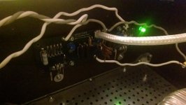
I knew I was building something on the bleeding edge of what was possible with this design, but I didn't expect it to be quite as harry as it is. One might wonder what's wrong with me that I'd want to push it further. I'm learning stuff. I've attached a pic of an amp board. I'm sure there's prettier amps out there, but it works and it's quiet. There will be a second effort at this at some point. That largely depends on when I stop paying lawyers.
Attachments
I actually cannot find a datasheet of the IRFP240 or 9240 that has the DC graph, so my apologies. The newer Vishay datasheets do not have them either.
I use linear derating, 150W/25C and 0W/150C leads to an allowable dissipation of exactly 30W at 125C case temp (we get this by ((150-0)/(150-25) = 1.2W/C and then multiplying it by the actual case temp difference from 25C).
I agree with Hikari that 1A is not the optimal experience for an F5, and also that your temperatures seem excessive. It would be best to drop the rails and increase the bias, and ideally a fan on the sinks. 20C difference between the MOSFET case and heatsink surface is simply unacceptable and indicates poor interface performance - either material or installation.
Lots to look at.
I knew I was building something on the bleeding edge of what was possible with this design, but I didn't expect it to be quite as harry as it is. One might wonder what's wrong with me that I'd want to push it further. I'm learning stuff. I've attached a pic of an amp board. I'm sure there's prettier amps out there, but it works and it's quiet. There will be a second effort at this at some point. That largely depends on when I stop paying lawyers.
Nothing is really bleeding edge or unstable (except for your jfets, potentially) here. It's more an issue of priorities (wattage, bias, heat).
If that's a 4U chassis I am a bit surprised you can't get more bias out of it but maybe that's normal, I've only had a dual pair f5 in a 5U chassis which was able to get 2A bias with 24V rails. Is it 34V rails loaded or unloaded?
If you do decide on 24V rails transformers are all over ebay. I just bought a 600VA Amveco for $40 shipped.
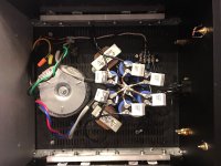
Anyways, I would get some mica (if you don't have any I will send you 4) and back the bias down until the heatsinks are 55c and go from there...the unusually high temps could be an indicator of oscillation or something wrong. If you have an IR temp gun check the source resistors (big blue ones)...You say you don't like the high end of the amp? Makes me wonder.
Also, what's going on with your feedback resistors? They should all be 3W (5W is probably safer with your rail voltage), I see a big dale in there but it looks like a 1/4W next to it?
And please tell me you are not trying to drive those big 3 ways (the 8 ohm rating and 92db spec is what I would call "optimistic") with a buffer or just a volume pot. This amp has 15db of gain. Better have something with gain in front of it.
Make sure you use spring washers on the mosfets and make sure mosfet bolts are tight (not stupid tight though).
The pressure applied between the mosfet and thermal pad also affects case temperature.
Use the thermal pads sold in the diyaudio store, I can vouch that they are far superior to generic silicone thermal pads.
The pressure applied between the mosfet and thermal pad also affects case temperature.
Use the thermal pads sold in the diyaudio store, I can vouch that they are far superior to generic silicone thermal pads.
Make sure you use spring washers on the mosfets and make sure mosfet bolts are tight (not stupid tight though).
The pressure applied between the mosfet and thermal pad also affects case temperature.
Use the thermal pads sold in the diyaudio store, I can vouch that they are far superior to generic silicone thermal pads.
Or do this
")
Attachments
- Home
- Amplifiers
- Pass Labs
- F5 power amplifier