you need to slightly increase input JFet drain resistors ( in parallel with pots) , to ensure some leeway for setting
I believe that you mean that you can't move it further ..... already ending pot's travel ?
No the pots are where they need to be for .6v bias. I turned them all the way open (no resistance) and offset stayed at 170mv, then I closed them a few turns at a time to gradually bring bias to .6v, and offset never changed.
I noted from the past that closing P1 normally increases offset and closing P2 reduces it. In that way I was able to "walk" the offset to zero as the bias came up. Not now.
That's the kind of offset I was seeing when I had the BJT's in there to limit current. I was also getting about .07V through the input jacks. But since you're getting bias through the source resistors, I don't see how that could be the issue. Those are the same boards I used. Is there voltage at the input jacks? What are the actual rail voltages? What are the voltages at the BJT legs?
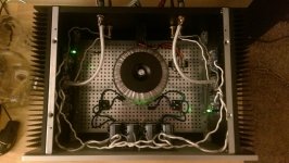
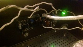
Thought I'd toss a couple pics of mine out there....
Thought I'd toss a couple pics of mine out there....
Attachments
Yes. Ground to leg. I seriously doubt that's the issue though given your rails are actually below spec. Mine are running at 34.5V and thats why Q5 and Q6 we're opening with the stock resistor values.-22.77 +22.87 rails, zero volts at the input. Are the BJTs Q5 and Q6? Do I just check each leg with the negative lead on the ground?
I just want to be clear I'm no seasoned pro at this. This was my first amp. I'm just tossing out stuff that I tried or would try in order to figure out what the circuit is doing. And to that effect, I'd start wondering what the voltage is doing at the JFET drain resistors.
Yes. Ground to leg. I seriously doubt that's the issue though given your rails are actually below spec. Mine are running at 34.5V and thats why Q5 and Q6 we're opening with the stock resistor values.
I just want to be clear I'm no seasoned pro at this. This was my first amp. I'm just tossing out stuff that I tried or would try in order to figure out what the circuit is doing. And to that effect, I'd start wondering what the voltage is doing at the JFET drain resistors.
I'm getting 4.93v across R6 and 4.94v across R5. It should be 4.2, not sure if this is indicative of a problem.
I'm getting 4.93v across R6 and 4.94v across R5. It should be 4.2, not sure if this is indicative of a problem.
Did you build this to the layout in the F5 article or the F5 Turbo article?
Did you build this to the layout in the F5 article or the F5 Turbo article?
This is a completely stock F5 using the 3.0 boards. Something changed somewhere.
This is a completely stock F5 using the 3.0 boards. Something changed somewhere.
I understand that, but the boards you used aren't laid out and marked according to the layout shown in the original F5 article. They're laid out and marked according to the F5 diagram in the F5 Turbo article. If you stuffed the board according to the original article you've probably got resistors in the wrong places.
McQuaide, unless I am totally missing something:
The offset should reflect the difference between how "hard" Q3 is driven relative to Q4. For the picture that you showed earlier, you are getting 3 mV difference in the bias between Q3 and Q4. So, your offset should be reading 0.003 V. It looks like you are either measuring the offset from the wrong place, or as Kosst said above, that the circuit is not a stock circuit. Andy
The offset should reflect the difference between how "hard" Q3 is driven relative to Q4. For the picture that you showed earlier, you are getting 3 mV difference in the bias between Q3 and Q4. So, your offset should be reading 0.003 V. It looks like you are either measuring the offset from the wrong place, or as Kosst said above, that the circuit is not a stock circuit. Andy
I understand that, but the boards you used aren't laid out and marked according to the layout shown in the original F5 article. They're laid out and marked according to the F5 diagram in the F5 Turbo article. If you stuffed the board according to the original article you've probably got resistors in the wrong places.
McQuaide, unless I am totally missing something:
The offset should reflect the difference between how "hard" Q3 is driven relative to Q4. For the picture that you showed earlier, you are getting 3 mV difference in the bias between Q3 and Q4. So, your offset should be reading 0.003 V. It looks like you are either measuring the offset from the wrong place, or as Kosst said above, that the circuit is not a stock circuit. Andy
Bingo, this is the first time I've biased it since adding the speaker protector board and I was measuring at the binding posts. Measuring at the board output yields zero offset.
This makes me wonder why the speaker protector is adding DC.
I didn't get any diagram with my boards. I went straight off the diagram for the F5 in the F5T article and made the deletions for the higher power output.
Not sure what to tell ya about the protection board. Bad ground?
I hope you get it sorted out. That thing will only sound better the more you use it!
Not sure what to tell ya about the protection board. Bad ground?
I hope you get it sorted out. That thing will only sound better the more you use it!
I was reading Nelson's article on finding the sweet spot, and wanted to add a P3 trimmer to my F5 to balance the JFETs.
I've already laid out my boards to the F5 "production" schematic, but I noticed that the "F5 w/P3" schematic includes a couple of changes to the temp compensation cct (thermistor connected to V+ vs. after the .47R) and the current limiting cct (Q5-base-to-V+ changed from 150R to 100R). I presume these have more to do with the MOSFET change (IRFP9240 -> FQA12P20) than the addition of the P3 trimmer?
Sorry for the noob questions; I'm still getting my head around this whole analog domain.
Thanks,
Jeff.
I'm no expert, but I'm going to guess the placement of TH1 and TH2 after the source resistors allows for better tracking. The 100R and 150R values are strictly about current limiting. The values are contingent upon where you want Q5 and Q6 to open and limit output. Neither changes have anything to do with the choice of output MOSFETs.
Hi Kosst,
I went back and read the section it the manual about the current limiting cct, and I agree with you on the resistor change: it looks like it raises the hard limit from 10A (150R) to 14A (100R). I don't plan on running the bias particularly hot, so I think I'll stick with 150R.
I had a look at my PCB design and it should be easy enough to move the thermistor, so I think I might make that change.
Cheers,
Jeff.
The bias and current limiting don't have much interaction. The current limiting steps in as the amp transitions into class AB or if the outputs are shorted. The 10 amp number comes the current drawn by a load of about 2.5 ohm. It's a good number if your speakers have some mean impedance dip like mine do. You'll still want to bias as high as you feel safe in going because that's what dictates the class A envelope. Biasing it to the 25 wpc RMS is very safe assuming adequate heatsinking. I've biased mine up to 1.1 amp (.515V across the source resistors on 34.5V rails) and yeah, it runs piping hot, but it's stable and the MOSFETs never reach over 80C. It's doing a 75 watts peak in class A.
I found a stash of NOS Harris (91 date code) IRFP9240s. I ordered 20 at $2.50ea, but I only need 10 or so. Give a holler if you've any interest in the other 10.
Cheers,
Jeff.
PS: if I get hit for the VAT coming into the EU, they'll be $3.12ea. Other folks in the EU will be used to that, but I'm not likely to do the paperwork to get it back if they go back to the US, so they'd still be $3.12. An Post sends me a VAT bill about 1/2 the time, so one never knows....
Last edited:
Hey!
I am getting a little bit confused about the proper numbers concerning impedance and sensitivity. So, I have a speaker with 83 db (2.38V/1m) and 4 Ohm impedance. My preamp has an ouput voltage of 2.25V RMS.
Can I use this speaker with my F5?
I know that the F5 has 50 Watts at 4 Ohm Impedance, but I am not sure how this connects with the sensitivity.
Thanks a lot, Philip
83dB is moderately loud (a bit louder than a garbage disposal). That figure is presumably @ 1w @ 1m.
Sound falls off by the square of the distance. So if you're sitting 10' (3m) away from the speaker, you'll need 9w to generate the same volume.
Every 3dB louder takes twice the power. Humans experience "twice as loud" as roughly 10dB. So you need roughly 10 times the wattage to go twice as loud. Since your F5 won't push 90w, you're only going to get to about half-again as loud (around 90dB at 10').
Only you can answer if that's loud enough. It's certainly not live rock concert levels (100+dB); on the other hand it would be loud enough for some.
Cheers,
Jeff.
(PS: this is how I understand it, but I'm no expert. Corrections welcome.)
(PPS: that's a pretty inefficient speaker. I think the majority of speakers would be in the mid- to upper-80's, while high-efficiency designs would be in the upper-90s into the 100s.)
- Home
- Amplifiers
- Pass Labs
- F5 power amplifier