Your leads are still not twisted. You should twist the transformer leads, both primary and secondary. If I remember correctly those primary leads that work their way over to under the rectifier boards connect to your NTC. Shorten that and keep the NTC nearer to the transformer.
You have a ground connection under a pile of tape to the left of the PEM in the second picture. Photograph that without the tape - it looks like the connections may be incorrect.
Also I don't see a connection directly from the PEM ground to the chassis. If there isn't a connection directly from the PEM ground to the chassis it is a safety issue and must be corrected before anything else is done.
To expand on AndrewT's comments, be sure to test the second channel by itself, without the other channel connected to anything. This will tell you if the issue is that particular channel or a ground loop.
Route the right (in the second picture) output leads further from the transformer.
Are the input connections isolated from the chassis?
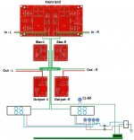
@ acumos - Something that was very helpful for both me and the members giving assistance for a hum problem was a diagram. Can you use a simple paint/graphics program to draw out all connections? This one is a bit overdone (can even be just a hand sketch) but something similar (showing exactly what you have now) would be a useful debugging aid.
Attachments
Last edited:
Ok. I'm back. New mosfets and now it's working again, but the same old hum is present in the two channel. Now I have solid core twisted input.
You have a loop in the chassis that the external IC's complete.
Wrap one internal input around the ground wire of it's board to the center supply then up the other ground wire to the other channel, then wrap it around the other intermal input wire pair to the backplate, then keep it tight along the back chassis panel to the input jack.
jn
Your leads are still not twisted. You should twist the transformer leads, both primary and secondary. If I remember correctly those primary leads that work their way over to under the rectifier boards connect to your NTC. Shorten that and keep the NTC nearer to the transformer.
You have a ground connection under a pile of tape to the left of the PEM in the second picture. Photograph that without the tape - it looks like the connections may be incorrect.
Also I don't see a connection directly from the PEM ground to the chassis. If there isn't a connection directly from the PEM ground to the chassis it is a safety issue and must be corrected before anything else is done.
To expand on AndrewT's comments, be sure to test the second channel by itself, without the other channel connected to anything. This will tell you if the issue is that particular channel or a ground loop.
Route the right (in the second picture) output leads further from the transformer.
Are the input connections isolated from the chassis?
It's very hard to twist the trafo leads, cause they're bulky. I've changed the position of the ntc away from the input output.
The ground from pem goes to one ntc lead, the same lead has a fork to chassis, the other lead is connected to psu gnd.
I'v moved away the output from the trafo.
If i check continuity between inputs and chassis I have 260 ohm with central, and continuity with input gnd.
Is it normal to have continuity between the metal disc of the mosfets and chassis? What should be the behavior of the three leads?
Last edited:
????????????????You have a loop in the chassis that the external IC's complete.
Wrap one internal input around the ground wire of it's board to the center supply then up the other ground wire to the other channel, then wrap it around the other intermal input wire pair to the backplate, then keep it tight along the back chassis panel to the input jack.
jn
Well, after 6 months of slowly gathering everything, reading re-reading re-re-reading this thread and all the other wonderful info about this amplifier I could find, I have finally finished my F5! It bias'd up super easily and after playing for a day on my bench with some cheap speakers, it is now in my main system. This is the best amp I have ever used, hands down.
This was the first amp I've ever put together and I would like to thank everyone who posts here, you have been a tremendous help. I didn't ask too many questions, due to the wealth of info and all the awesome build guides. I think I read 6L6's and the main tutorial hundreds of times.

Nice build! I see you found the Mills .47R's and Mundorf caps too, & some pretty posh input resistors..
")
Last edited:
Maybe it's normal because the board is connected?Houston we have a problem. I have continuity between chassis and several leads of mosfets and diodes in psu.
^ That is not normal at all, acumos. Pull the offending boards and check for shards of metal or other cause of the short - likely stuck in the isolator. If you can't find any clean carefully and replace the isolators with new ones. Then resume troubleshooting.
Any twist in the PSU leads is better than having a pair of antennae. Anything that gets them closer together.
The PEM ground must go UNINTERRUPTED to the chassis. There is no need to connect the ground loop breaker to the chassis at the same spot.
Please explain this:
Are you measuring the ground of the input connectors or signal side? Central means the star ground?
Any twist in the PSU leads is better than having a pair of antennae. Anything that gets them closer together.
The PEM ground must go UNINTERRUPTED to the chassis. There is no need to connect the ground loop breaker to the chassis at the same spot.
Please explain this:
If i check continuity between inputs and chassis I have 260 ohm with central, and continuity with input gnd.
Are you measuring the ground of the input connectors or signal side? Central means the star ground?
acumos - have you considered swapping just the F5 boards side to side to determine if the problem is on a PCB and not the wiring leading to it?
Still suggest a diagram. As you do that, the one step at a time process can reveal errors. Similar to proof reading your term paper.
Still suggest a diagram. As you do that, the one step at a time process can reveal errors. Similar to proof reading your term paper.
Last edited:
I tried disconnecting the board from the heatsink, this time without power. And I have 160 ohm between some mosfet pin and the chassis.
About the gnd from pem to chassis I followed the f5 build guide.
If I put a probe in the chassi and the other one in the central rca pin I have 260 Ohm, 0 ohm with lateral rca pin.
About the gnd from pem to chassis I followed the f5 build guide.
If I put a probe in the chassi and the other one in the central rca pin I have 260 Ohm, 0 ohm with lateral rca pin.
Last edited:
acumos - have you considered swapping just the F5 boards side to side to determine if the problem is on a PCB and not the wiring leading to it?
Still suggest a diagram. As you do that, the one step at a time process can reveal errors. Similar to proof reading your term paper.
I have the same hum in the all the two channel.
I'm writing the diagram, now I must go to work...
Last edited:

260 ohms from signal input to ground means a build error. Remove your signal leads from the RCA jacks and measure hot to ground again. Concur with Sangram if you meant to write output.
If the PEM ground does not go directly to the chassis you misunderstand the build guide. IIRC, Jim used the same place to connect the PEM and signal grounds, but the PEM ground wire goes directly to the chassis.
If the PEM ground does not go directly to the chassis you misunderstand the build guide. IIRC, Jim used the same place to connect the PEM and signal grounds, but the PEM ground wire goes directly to the chassis.
here's another one (me) with a humming issue.
F5 v3 dualmono. inputsignalground kept separated (meaning left/right) and isolated from chassi 'til the cvillierboards. each channel has got a groundstar with cl-60 connection to
earth/chassi.
with disconnected input the machine is dead silent- no hiss, no hum
same with handheld mp3-player as input.
but as soon as i plug in the cd-player there's a hum but only with both channels pluged in.
if i pull one out, no matter left or right the hum is gone.
any suggestions/ideas?
Nice build! I see you found the Mills .47R's and Mundorf caps too, & some pretty posh input resistors..
Thanks! My plan to keep this build around $700 quickly went out the window. Spreading the cost over 6 months allowed me the chance to convince myself that I needed to gold plate everything. At least it will stop me from tinkering with it, as there is really nothing to upgrade.
- Home
- Amplifiers
- Pass Labs
- F5 power amplifier