Changing the feedback resistors to 220ohm will not only change the gain but also how the F5 sounds and I didn't like that.
do you think 3 Farad per channel is enough "Capacitance" power for F5 ?
Pyramid Royal Blue CAP300DBL 3 Farad Digital Car Audio Capacitor : VMInnovations.com
Pyramid Royal Blue CAP300DBL 3 Farad Digital Car Audio Capacitor : VMInnovations.com
Last edited:
Another stupid post!
I know I´m asking a lot of questions without any action in several threads these days, but its coming..
Two questions that are answered in a lot of places already, but always a bit out of context:
All these different resistor values. The schematics have a lot of different values, and most often at the input. Is it really the same? I can not find the 4.75k values anywhere!
And can I simply switch between fairchild, irf and toshibas without changing any other parts? I understand that bias needs to be reset.
Thanks!
Royal-Blue
It does have somewhat of a post-'80s terrorist beumb appeal, nice to blow up a contemporary venue with.
(amusing that automobile sound parts generally have the appearance of originating out of a Chinese dance club, a very gay one)
Or Rixsta needs to have Surge explained.
Some proof
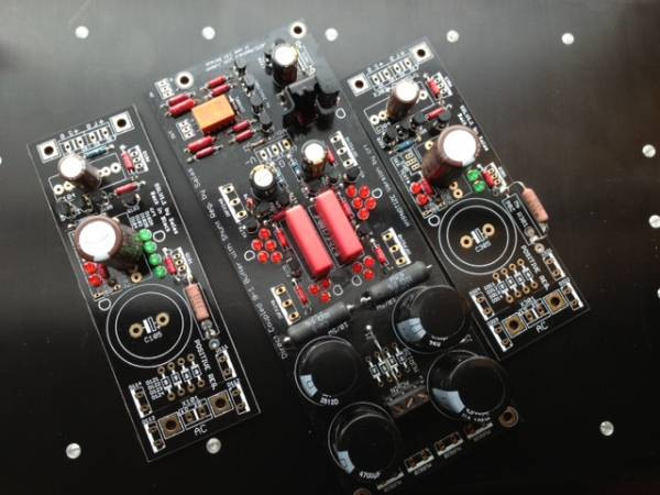
I know these boards are not for the f5, but the heatsink beneath is! I made a lot of holes in it yesterday, but they are not tapped just yet.
The boards are, obviously, dcb1 and salas regulators. The regulators are for a simplistic that also is in the making.")
I know these boards are not for the f5, but the heatsink beneath is! I made a lot of holes in it yesterday, but they are not tapped just yet.
The boards are, obviously, dcb1 and salas regulators. The regulators are for a simplistic that also is in the making.
Jal,
passive components come in set values with a very few additions to the range.
The normal range for capacitors is E3 & E6.
Resistors come in E6, E12, E24 and some come in E48, E96 and even E192.
4k75 is not from E24.
4k7 is a E12 and E24 and is very generally available.
Note that 4k75 is ~ 1.06% above 4k7 and most circuits will work properly with an error this small.
Those are going to be expensive and messy when they blow up due to continuous over-voltage...
Its fun
It does have somewhat of a post-'80s terrorist beumb appeal, nice to blow up a contemporary venue with.
(amusing that automobile sound parts generally have the appearance of originating out of a Chinese dance club, a very gay one)
Or Rixsta needs to have Surge explained.
yes it does hahaBut seriously how about my Jean Hiraga 20w that runs off 12v, would those caps do for that, or is it still insanity ?
2 in series pr rail can handle the 24V rails
...and will halve the capacitance...
Changing the feedback resistors to 220ohm will not only change the gain but also how the F5 sounds and I didn't like that.
There is a forum topic called F5 Listening Impressions started by Bear and this has lot of comments and suggestions about all sorts of mods, including feedback changes and how it affects sound. In fact I think it would be really cool to start a new topic called "F5 mods and such" and have a table that F5 builders could fill in to say what mods they've made (FB, JFETs, BIAS, outputs, PS, etc etc) and what listening experience they've had with those changes in comparison with the stock amp. Also what music source, pre-amp, speakers and enclosures volume they've had and how big the listening room was. I think lot of people would be interested to see this. There were lot of mods made and it would be nice to have it all summarized in a single place.
Last edited:
...and will halve the capacitance...
yes. but i don't realy see a problem With "only" 1.5F pr rail.
and one may want to have a CRC supply. then there will be 3F pr rail.
but i would not use this kind of caps
but i don't realy see a problem With "only" 1.5F pr rail.
Your transformer and rectifier bridge will.
Your transformer and rectifier bridge will.
not more then with 3F pr rail
and this is why i also said that i would not use this kind of caps.
How long should we expect 1.5F or 3F capacitors take to charge up?
What maximum current should we set for the charge current limiter?
Where best to fit that charge current limiter?
Can we start using the amplifier when the capacitor charge has reached 50% of final voltage or 70% or 80% or 90% or 95% or 99%?
What maximum current should we set for the charge current limiter?
Where best to fit that charge current limiter?
Can we start using the amplifier when the capacitor charge has reached 50% of final voltage or 70% or 80% or 90% or 95% or 99%?
not more then with 3F pr rail
Not exactly less either.
If one jumps off a cliff, whether the drop is 1500 or 3000 feet, is of no importance, only the edge is.

What does matter is how those cheap car things are constructed.
Reliable lytic brands manufacture caps in a 20Vdc (to 25) rating, three times lower ESR, with value numbers of 1F and above.
But they charge at least five times the retail of a China transgender. (Digital my A..)
Either way, charging 2x1.5F total or up by a conventional setup sounds scary.
Last edited:
- Home
- Amplifiers
- Pass Labs
- F5 power amplifier