High temp on source resistor
Hello guys,
last night i took the chance of raising the bias level on my F5 monos a bit, just to hear if there is any difference. My loudspeakers are the well known DTQWT's by Troels Gravesen.
Their sensitivity is 95 dB/2.8 volts, with minimum impedance of 6 ohms, a nice load for the F5's.
I can say that the difference, with bias raised to 0,740mV (1,57A) is astonishing compared to the standard 0,590mV ! Now I really understand how high is this amp's quality.
Level of detail, soundstage and pinpoint image are on par with a triode amp (e.g. a SunAudio 300B I had the opportunity to hook to my speakers), with great bass frequencies added.
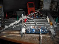
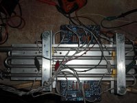
My F5's heatsinks are really huge. See here:
http://www.diyaudio.com/forums/pass...-your-diy-pass-amplifier-131.html#post3124930
With a room temperature of 20C (68F) I'm getting (measured by my multimeter's temp probe)
heatsink : 35C (95F)
mosfet case : 55C (131F)
R11/R12 surface: 75C (167F)
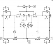
The source resistors are Mills MRA-5 (0,47ohm, 5W). I didn't install any temp controlling diode nor protection circuit (see schematic, as found some time ago on this thread).
Should I be concerned about the resistor temperature ? I can't find on the Mills' datasheet an actual suggested temperature range. Should I replace them with the MRA-12 (12W) ones ?
What bias level and temperatures can be considered to be safe ?
I'm not trying to set a 2V level of course, but I would like to keep it around 0,7V since the sound quality in my setup is really higher than the standard.
Thanks a lot in advance. Have a nice weekend
Hello guys,
last night i took the chance of raising the bias level on my F5 monos a bit, just to hear if there is any difference. My loudspeakers are the well known DTQWT's by Troels Gravesen.
Their sensitivity is 95 dB/2.8 volts, with minimum impedance of 6 ohms, a nice load for the F5's.
I can say that the difference, with bias raised to 0,740mV (1,57A) is astonishing compared to the standard 0,590mV ! Now I really understand how high is this amp's quality.
Level of detail, soundstage and pinpoint image are on par with a triode amp (e.g. a SunAudio 300B I had the opportunity to hook to my speakers), with great bass frequencies added.
My F5's heatsinks are really huge. See here:
http://www.diyaudio.com/forums/pass...-your-diy-pass-amplifier-131.html#post3124930
With a room temperature of 20C (68F) I'm getting (measured by my multimeter's temp probe)
heatsink : 35C (95F)
mosfet case : 55C (131F)
R11/R12 surface: 75C (167F)
The source resistors are Mills MRA-5 (0,47ohm, 5W). I didn't install any temp controlling diode nor protection circuit (see schematic, as found some time ago on this thread).
Should I be concerned about the resistor temperature ? I can't find on the Mills' datasheet an actual suggested temperature range. Should I replace them with the MRA-12 (12W) ones ?
What bias level and temperatures can be considered to be safe ?
I'm not trying to set a 2V level of course, but I would like to keep it around 0,7V since the sound quality in my setup is really higher than the standard.
Thanks a lot in advance. Have a nice weekend
Attachments
A small heatsink may help. I had to install them on the Ohmites supplied with the Tech-DIY kit - because of high ambients, my resistors were hitting close to 70 degrees surface temps too.
I recently got the MRA-5 and MRA12 for a single F5 build (my Turbo is all MP930 Caddock), and the MRA12 is about 5x the size of the MRA-5. Fair warning. They simply are too big - bigger than the entire width of some F5 PCBs.
I recently got the MRA-5 and MRA12 for a single F5 build (my Turbo is all MP930 Caddock), and the MRA12 is about 5x the size of the MRA-5. Fair warning. They simply are too big - bigger than the entire width of some F5 PCBs.
> I provisioned parallel surface mount JFETs -- pairs of mmbf5460/mmbf5457 which get you close to the J74/K170 and are very inexpensive
With due respect, you can still get 2N5457 / 5460 at Mouser ion TO92.
So actually no real need to go SMD. But of course you may.
Furthermore, I would not describe them as close to 2SK170/ 2SJ74.
Just a few figures for comparison :
Yfs
2N5460 1~5 mS; 2SJ74 ca. 22mS
en
2N5460 60 nV/sqrt.Hz; 2SJ74 0.75 nV/sqrt.Hz
At most a replacement for 2SK246/2SJ103, IMHO.
Patrick
c_door,
At the risk of sounding a "nutter", I'd suggest you block some of the fins of your heatsink with something and get your power fets body up to about 75 - 80*C, heatsink temp to "whatever *C" (this isn't at all critical except for possible internal component's temp - well within the safe operating area of the devices and the amp definitely sounds better when hotter.
Also, try cranking up the current thru the Fets to about 1.7A+ (Fet dissipation about 40W ea @23V) while you're monitoring the fet case temp - expect another improvement in the amp's sound - IMO, naturally!
As Sangram mentioned, Caddock MP930 well recomended here.
740mV across 0r47 is only 1.2W
Why are you concerned at running the resistors at ~23% of their maximum Pd?
If the tempco is high then consider using a pair of 1r0 5W in parallel rather than one big resistor.
Maybe better still use three 1r0 2W giving an effective 0r333 6W and with ~525mVrs you end up at your new 1.57A of bias.
Why are you concerned at running the resistors at ~23% of their maximum Pd?
If the tempco is high then consider using a pair of 1r0 5W in parallel rather than one big resistor.
Maybe better still use three 1r0 2W giving an effective 0r333 6W and with ~525mVrs you end up at your new 1.57A of bias.
Last edited:
> I provisioned parallel surface mount JFETs -- pairs of mmbf5460/mmbf5457 which get you close to the J74/K170 and are very inexpensive
With due respect, you can still get 2N5457 / 5460 at Mouser ion TO92.
So actually no real need to go SMD. But of course you may.
Furthermore, I would not describe them as close to 2SK170/ 2SJ74.
Just a few figures for comparison :
Yfs
2N5460 1~5 mS; 2SJ74 ca. 22mS
en
2N5460 60 nV/sqrt.Hz; 2SJ74 0.75 nV/sqrt.Hz
At most a replacement for 2SK246/2SJ103, IMHO.
Patrick
2N5457 are not in stock at Mouser -- i got some of the last ones when Dick Marsh wrote his headphone amp article for Linear Audio.
NP stated in the original article that the output noise of the completed amplifier was something like 30uV in a 20-22kHz bandwidth. The first F5 I built with K170/J74 was a bit better than this, and the ones I have subsequently experimented with using the 2N5460/57 are right around 30uV. The lower transconductance isn't helpful to getting the best THD%
The SMT devices are about $0.30 each if you buy 25 -- and as you'll be matching the devices it's a small penalty to pay.
J,
what equipment do you use to enable 30uV of output noise to be measured/compared?
AP2722 set to 20-22kHz bandwidth.
I've also written an AP Basic macro for noise measurement -- you have to integrate the measurements for a few seconds. I experimented with the number of measurements/iterations until they were stable within a few percent. The tables in the Linear Audio article on regulators used these macros.
With a room temperature of 20C (68F) I'm getting (measured by my multimeter's temp probe)
heatsink : 35C (95F)
mosfet case : 55C (131F)
R11/R12 surface: 75C (167F)
What bias level and temperatures can be considered to be safe ?
This requires a little calculation:
The rated junction temperature of the Mosfets is 150C
The thermal resistance of the junction to case is 0.69 deg/watt
The case temperature + thermal resistance * watts cannot exceed 150C
So Watts * .69 < 95C, and Watts < 137 for the case temp = 55C
This of course is the absolute maximum. The rule of thumb is that every
10C reduction in junction temperature doubles the life of the transistor.
Thanks mr. Pass for taking care of my question! And thanks to everybody of course.
I'll give a try to those 30W resistors, to be completely safe
This requires a little calculation:
The rated junction temperature of the Mosfets is 150C
The thermal resistance of the junction to case is 0.69 deg/watt
The case temperature + thermal resistance * watts cannot exceed 150C
So Watts * .69 < 95C, and Watts < 137 for the case temp = 55C
This of course is the absolute maximum. The rule of thumb is that every
10C reduction in junction temperature doubles the life of the transistor.
And how long is the lifetime for eample irfp240 at 55C?
Whats your experienced data?
Then I know for how long i have fun with my amps
And how long is the lifetime for eample irfp240 at 55C? Whats your experienced data?
I run them in production at 55 on the sinks. This translates to maybe
65-70 case. They seem to run forever.
![url]](/community/proxy.php?image=http%3A%2F%2F%5Burl%3Dhttp%3A%2F%2Fpic.free.in.th%2Fid%2Fc8921f25bed9647b55525b9b8227cf19%5D%5BIMGDEAD%5Dhttp%3A%2F%2Fimage.free.in.th%2Fz%2Fik%2F5picture028.jpg%5B%2FIMGDEAD%5D%5B%2Furl%5D&hash=5e6689c71560e83da9a2f3dd562911ee)
- Home
- Amplifiers
- Pass Labs
- F5 power amplifier