How much ripple on the PSU is accetable? I am using 36,000uF - 4 x 0.47ohm - 36,000uF, for each channel. I am using a copper plate to tie the four caps together. I'm taking the ground off two corners of the plate. What I'm seeing is more noise depending on which of these two ground points I measure from. I get 26mVAC between one of the corners and the closest cap which is the final cap on the positive rail. If I measure from the other ground point to this same cap, I get 75mVAC or so. I am getting 150mVAC or so on the first cap after the rectifier bridge. I was getting more like 1mVAC on my F4, hence the concern.
Here is a bad cell phone pic.
Here is a bad cell phone pic.
An externally hosted image should be here but it was not working when we last tested it.
Well I don't think it's a PS issue at this point... Pulled one of the input cables out accidentally when I was troubleshooting, and the noise vanished... So, with either channel connected and the other disconnected, quiet as a church mouse, both channels connected, the buzz is back. It's not much, but enough to be noticeable with my 105dB/w horns. I don't think it can be a ground loop, even does it when connected to a battery powered JBOZ that's not connected to anything that's grounded...
Any ideas?
Roscoe

How about a cable placing issue: twist the two input cables around each other, to make a twisted pear. If there is an opening between the two cables it might pick up EMC radiation - from power lines, trannies, or even from the hydro electric company far away.
How about a cable placing issue: twist the two input cables around each other, to make a twisted pear. If there is an opening between the two cables it might pick up EMC radiation - from power lines, trannies, or even from the hydro electric company far away.
I'm at work now, so I can't try that. Last night, I did hook up a single cable to the two inputs, and the noise appeared. Just hooking the input jack shields together with a clip lead does NOT cause the noise....
Roscoe
not sure I like a brick of copper, this way
but dont whether to prefer U- or H-profile
or you might try double bridge
and ground first between the last pair caps
( which means cutting a slit up the middle of ground copper plate, making the U-profile))
Interesting. So, something is indeed up with my PSU?
Ideally, each pair of caps for each channel will have a solid ground connection and then these two grounds would be connected at the output? I might be able to rearrange things to get this layout.
Roscoe - Does it hum with both inputs shorted?
I'll try that this evening....
Roscoe
Hi, this is my first non french post, hope you all will understand...

I'd like to make an F5 amp. The pair of F5 boards will be bought on the DIY store and components on Tech Diy company store.
I was thinking about the PSU: dual mono configuration, each channel will be made by a 250VA transformer, fast recovery rectifiers bridges and CRC cells, first cap 22000µF LL caps, R=0.5ohm and second caps 47000µF very low esr.
Which caps will be great for this use?
Sorry for my bad english
Damien
Roscoe - Does it hum with both inputs shorted?
No. At this point, it's time to put the cover on, and ship it out there, I'll take some ferrites to try if it's a problem in Dad's system...
Thanks guys.
Roscoe
Well I don't think it's a PS issue at this point... Pulled one of the input cables out accidentally when I was troubleshooting, and the noise vanished... So, with either channel connected and the other disconnected, quiet as a church mouse, both channels connected, the buzz is back. It's not much, but enough to be noticeable with my 105dB/w horns. I don't think it can be a ground loop, even does it when connected to a battery powered JBOZ that's not connected to anything that's grounded...
Any ideas?
Roscoe
I had a similar issue in a stereo amp. Hum/buzz only when something was connected to the input. Makes you crazy!
It had a power supply board off eBay, one of the red ones. After much pulling of the hair, frustration, so on, hours later, I looked at the U shaped grounding trace and the ground wires 2.5 inches apart down the trace from the main ground point. Could this be? A few inches of copper for the speaker posts and boards? I went to a star type ground for all the amp ground wires, instead of the power supply circuit board grounding. And the hum went way down.
Anybody want to buy a used red power supply board?
Grounding is so important, don't assume that lots of copper will prevent hum from current loops.
Hope this helps.
Rush
Hi, this is my first non french post, hope you all will understand...
I'd like to make an F5 amp. The pair of F5 boards will be bought on the DIY store and components on Tech Diy company store.
I was thinking about the PSU: dual mono configuration, each channel will be made by a 250VA transformer, fast recovery rectifiers bridges and CRC cells, first cap 22000µF LL caps, R=0.5ohm and second caps 47000µF very low esr.
Which caps will be great for this use?
Sorry for my bad english
Damien
Rifa's are a good choice having very low esr but having said that I used 33,000uf Panasonic's in a CRC configuration in my F5 build with excellent results and saved money in the process.
If my French was as good as your English I would be a happy man

Right for Rifa caps, I saw their characteristics and they seem pretty good. I think use BHC 10000µF/40V LL caps just after rectifier bridges, then Rifa 47000µF/40V very low esr (0.008ohmsRifa's are a good choice having very low esr but having said that I used 33,000uf Panasonic's in a CRC configuration in my F5 build with excellent results and saved money in the process.
)Is someone ever use carbon composition resistors in a FirstWatt amp? what do you think people about that?
This amp should be as good as possible because I'm already using a quite good valve amp (a very old and very modified Jolida, KT90ei push pull in triode mode) and my F5 project is to surpass this one.
ThanksIf my French was as good as your English I would be a happy man
Damien
So, I rearranged things and am using some heavy copper wire in a U shape. I'm getting 125mVAC before the CRC and 35mVAC after. Both rails are close to the same here. What is acceptable?
In addition to the above, one more question.
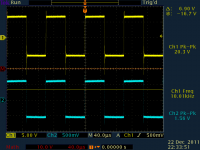
Things look great at 8 ohm load. The amp clips at 40 Vpk-pk. The square wave looks nearly perfect at this point. I'm very happy.
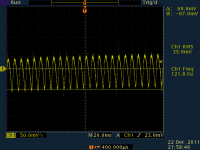
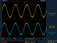
I'm also interesting in driving a pair of AKG K1000 headphones. They are 120 ohm impedance and rated at 1W maximum and are 74dB/W. So, I figure about .4W to get to 100dB. Once I get close to this (using a dummy resistor), I start to get some strange behavior on the falling edge of a square wave (see attached) and even get some nasty stuff on the sine wave output (nearly vertical lines on the bottom half of the sine wave, didn't remember to get a capture). The nastyness starts once I exceed 27 Vpk-pk. I'm thinking I probably need some sort of compensation, or way to deal with these headphones. Any recommendations? It's strange to only see on the bottom half of the waveform.
The other deal is (and related to my quoted question above) it's unclear what the noise floor of this combo will be. With no source I'm getting 35mV pk-pk noise on the output. The frequency seems to jump around, it's hard to measure. Is there a way to measure (and formula) whether or not one would hear a hum or buzz, without listening? I'd assume it would depend on the sensitivity of the speakers, and how far one was away from them and what not... but such a calculation would be useful.
Attachments
The K1000s, the K701s and most of the AKG range of headphones are really best mated up with current drive o/p stage - I think, but don't really know for sure, that the problem here is related to the higher impedance load to the amp - perhaps you could drive an 8R load with your amp in the usual way and connect the headphones across that to see if the problem of distortion at 27V p-p is a function of the signal o/p exceeding your rails or just gross overload of the amp.
No doubt, a readjustment of the amps parameters could easily tailor the amp to suit the load for the 'normal' max power of the K1000 headphones.
You may find the DAO headamp (current buffer) more suitable for driving your K1000 or a low power version of the F3 amp.
... my 2 cents
No doubt, a readjustment of the amps parameters could easily tailor the amp to suit the load for the 'normal' max power of the K1000 headphones.
You may find the DAO headamp (current buffer) more suitable for driving your K1000 or a low power version of the F3 amp.
... my 2 cents
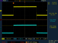
problem of distortion at 27V p-p is a function of the signal o/p exceeding your rails or just gross overload of the amp.
it's the latter. If I put a 8 ohm load in parallel, the issue goes away completely.
Any idea on what to add to the output? Perhaps a 22 ohm resistor with 47nF cap in series, across the output? I'll dig through my part box and try this first.
If you just wanted to use the amp to drive your headphones, I'd suggest that you reduce the amp's bias but as this will radically alter the cct operating conditions, don't think you'll get good results that way.
Perhaps you might find one of the Jean Haraga designs (l'Audiophile archive) more suitable for your requirements, possibly the "la Prophet", I think it was.
Pardon me, but why do you want to run your headphones over 100dB - even with the k1000s, that pretty loud for such a clean, clear punchy sound.
When setting the amp up, I found that the using my k701s extremely useful and found that not only does the amp sound better when heatsinks are over 50*C, but improves quite a bit more when the input jfets are also connected to the heatsink (didn't really notice it at first on the speakers).
Someone awhile back reduced the bias and increased the rails (with the cascode input transistors) and that apparently solved his problem concerning higher impedance speakers - perhaps this might be a possibility .....
Xmas greetings, and all that jazz!
- Home
- Amplifiers
- Pass Labs
- F5 power amplifier