Neutrality
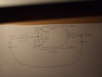
It is getting there but IMO your preaplifier / source has a mains suply which is connected to the earth at the soket and then the 2 cables feeding line in to the F5 are also connected (the screen on the cable)to the ground so you shold cut the connection to ground on the line in F5 sides otherwise you have the dreaded ground loop (2 actualy)
Normaly this is done on the F5 sides as it stops noise been fed to the amp troug the line in cables the ground connection is already there troug the mains sokets
as your pre should also have a star ground.
you are rigth,Why to use many output devices if not for increasing rail's voltage ?
but i think i can get beter control of dificult loads...
More output corrent.
My speakers are not high eficient.
Again My question is ,Hi,
In case of a not cascoded F5, with multiples outputs Mosfets pairs, like Melon Head do, can we benefit from Parallel jfets inputs or use Jfets with higter Idss like V instead of BL ?
Thanks
with higter Idss, can Jfets beter drive multiple output devices?
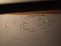
Put a CL-60 in the red cross point (as Nelson suggest). You're done with the loop.As this
You can put another one in the preamp green-cross.
Regards,
Regi
Edit: Sorry, forgot the attachment...
Attachments
Last edited:
you are rigth,
but i think i can get beter control of dificult loads...
More output corrent.
My speakers are not high eficient.
Again My question is ,
with higter Idss, can Jfets beter drive multiple output devices?
If you cascode and voltage divide across the jfets then you can increase Idss maybe as high as 14mA depending on voltage across jfets.
Hi regiregi22
I have the thermistors on the live and neutral (primary of the transformers)
I don't think that it is a good idea to put one of those on the ground they will increase the resistance of the earth (fault loop impedance) and compromise safety.
I mean that the position on which they are placed need to be chosen carefully
On the F5 manual Papa included TH1 between the common of the capacitor banks and the connection to the chassis ground IMO that connection is there to stop having a floating voltage, there should be no current at all flowing trough it under normal conditions.
The thermistors ad resistance (10 Ohms) to the ground it will not cut a ground loop if there is one
I don't have thermistors on the preamplifier they are used on the F5 to stop surges when charging the capacitors and I am planning to fit a relay&timer to bypass the 2 on the F5 once the capacitors are charged.
IMO a relay contact is beter than 2 metal oxide disk at 100C and any voltagge at the ground should be taken away with a zero impedence connection if possible as i like my fuses to blow as fast as possible if they realy have to.
I can see the point Ihquam is making about cross talk if you get in to it you be luky to get 20dB from the phono cartridge (briliant drawings and such qudos to Ihquam)
but we are cosidering ground loops where noise is introduced in the system and goes around and around in a loop idealy you need evvery point of the ground to be at zero volts which is impossible or just make shure that there is no loops for it to go around and around
Option B is the easy peasy one IMO
The commercial f5 all have the cl60 on the circuit ground - mains earth line. Another option is a pair of diodes back to back paralleled with a 10r power resistor and a 0.01-0.001uf cap rated >than the mains voltage.
Well worth doing as a routine matter plus has been used for years in the valve world.
Well worth doing as a routine matter plus has been used for years in the valve world.
Woodturner-fran
Fine by me but why?
What it does?
Do they stop ground loops if there is one?
I am not saying that is wrong to use them I just don’t like them.
Necessary on the motor of the fridge compressor and such but also one of the parts that eventually fails and quite a few fridges are in fridge even just because of that.
I just don’t like them because they work by getting hot they get really really hot
I saw few builds with them and bare wires near metal parts scary!!!
At least use ceramic spacers (Farnell PNo 8919275) or nick one of missus or daughter necklace with glass beads and use those to isolate the wires and Ceramic terminal blocks (Farnell 117 0355) to connect them, as eventually they will roast the connections.
PS Farnell number just so you can goggle up the picture not necessarily the best or cheapest
Fine to stop the surge when charging the capacitors on the F5 but once this is done why would you want to keep them there?
Don’t get me wrong I know very little and have seen same exceptional good pictures of your stuff I just would like to know why they are used I know even less about valves but I would like to learn.
And for this your input is very much appreciated
Regiregi may be right but in the crapy drawing I made some one may decide to fit one on the mains plug of the preamp and cause same serious damage.
Me think that we need a beter drawing showing where they are and it is my fault that I posted that Iquam work is much beter but it does not show the connections to the pre and such and most commercial cables have the screen connected to both ends and it does not need to be.
Thermistors are there for reasons that I don't fully understand Still it will not stop a ground loop yes?
The thermistor idea is that it has a high resistance cold, but as current starts to flow to ground, it heats up and the resistance drops. So in the "normal" case, it sits there cold and high resistance. But if a fault develops and current flows, it allows more and more to flow. Good example is the one in the live feed to the PS of the F5 - it starts cold, but as current is drawn, the CL60 heats up and in the end it stays warm, with low resistance presented to the power feed. In that application it acts as an inrush current suppressor - good where there are big toroids.
The back to back diodes present a similar resistance to small ground currents, but irreversibly break (diodes fuse short rather than open) when a larger one comes along.
Lastly, I'm only really a kit man - I don't have original ideas, nor do I pretend to have any EE knowledge at all - I'm pretty poor at all of that stuff. I've used a few of the above in builds however and they do work.....
Put a CL-60 in the red cross point (as Nelson suggest). You're done with the loop.
You can put another one in the preamp green-cross.
Regards,
Regi
Edit: Sorry, forgot the attachment...
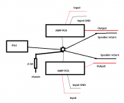
So if you put a cl-60 from psu gnd to chassis ground like the power supply example in the F5 manual, then the ground loop will be gone?
tanks woodturner
A kit man you may be but from what I have seen you deserve far more respect than quite a few "professionals" and patronising tutors we got here.
Agree with you 100% thermistors start cold at "hi" resistance and warms up to operating themperature and the resistance drop.
I got 2 on live and neutral feed to the trafo and they work (apart that I dont like them and that I bypass them after a shorth while)
Sorry I dont agree with the "stay warm" part to you it may be warm to me is really realy hot (hotter than a heat sink)
I am not shure why is there on the ground to me it looks like increasing the lenght of the earth cable
(and that cable is there for protection and used only when things go wrong )and if this is the case I would like for it to be as shorth and as thick as possible.
Still it will not brake a ground loop right?
So 2 questions now :
Will a thermistor breack the ground loop ?
No it will not IMO
What is the function of the thermistor between the capacitors common and the ground as shown on the F5 Papa Nelson PSu called TH1?

Originally Posted by carlomar View Post
you are rigth,
but i think i can get beter control of dificult loads...
More output corrent.
So, two pairs, biased at 1.3 A each, are enough for 25w class A into 2 ohms.
Hi Jacco
Sorry dont cathc your drift
I am preaty shure you can do much beter. What is the function of the TH1 in Papa drawing?
found this way beter than any I could possibly post
http://www.rane.com/pdf/ranenotes/Sound System Interconnection.pdf
To big to post but paste link on duda job done.
wikipedia good source as well
Sorry but yes, THEY WILL, that's why they are there. Because of the added resistance. Of course it will not cure ALL ground loop problems, but it will with the ones that are caused by mains protective earth. At least to a certain degree. In case of a fault, they carry big currents, so they get hotter. As they get hotter, their resistence falls, what allows the to carry even more current. Until your PROPERLY SIZED fuses blow.The thermistors ad resistance (10 Ohms) to the ground it will not cut a ground loop if there is one
Please someone correct me if I am wrong.
Anyway, said that, I prefer to have a back-to-back pair of diodes with a resistor and a capacitor in parallel. Using a diode bridge of 35Amps allow VERY big currents to flow for a short time. Even if you burn the diodes, the fail closing, so they will still conduct until the whole device is melted. Even melted, it will still conduct
 So a very big sized fuse would be installed if you reach this point.
Bksabath, what's the downside of having the CL-60s in the primary windings? Please, don't account those things you're afraid regarding bare wires and so. We asume a correct safety implementation, not leaving bare wires floating around the case (
)An expert should confirm me but, I am pretty confident it will.So if you put a cl-60 from psu gnd to chassis ground like the power supply example in the F5 manual, then the ground loop will be gone?
Yes, that's exactly the way to do it neutrality.
So it is ok to have your star ground point "floating" as long as it is connected to the chassis through a cl-60?
I just want to be sure.
- Home
- Amplifiers
- Pass Labs
- F5 power amplifier