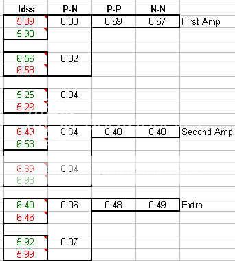
I found it very interesting when I populated the data I posted above in a different way. I basically got three quad P-N matches out of a set of 40 JFETs and one extra P-N matched set. I see why the matched sets are so much more expensive now. It takes a while to narrow it down!
I do have a question now though which I may have to find out when I finally get everything together. If given a choice between good P-N matching and P-P (or N-N) matching, which set would you go for? I am going to choose the tightest P-N set, which coincidentally has the worst P-P numbers. The next amp gets the set with more rounded numbers all around. Time will tell...
I do have a question now though which I may have to find out when I finally get everything together. If given a choice between good P-N matching and P-P (or N-N) matching, which set would you go for? I am going to choose the tightest P-N set, which coincidentally has the worst P-P numbers. The next amp gets the set with more rounded numbers all around. Time will tell...
I'm not sure what you mean by P-P or N-N matching??
Do you mean between two channels??
If so, I would likely opt for a decent match between the two channels if the choice was between that and "perfect matches" IN a channel but rather different between channels.
The reason is that the values that end up being used for the biasing will be closer between channels - which at least on paper means that the characteristics of the two channels will be closer.
You have a couple of good candidates in your spreadsheet shown...
Of course, this is really getting "fine" and the amps will work ok and probably not sound audibly different using even random Jfets, although maybe NP or others have other experiences with this amp...
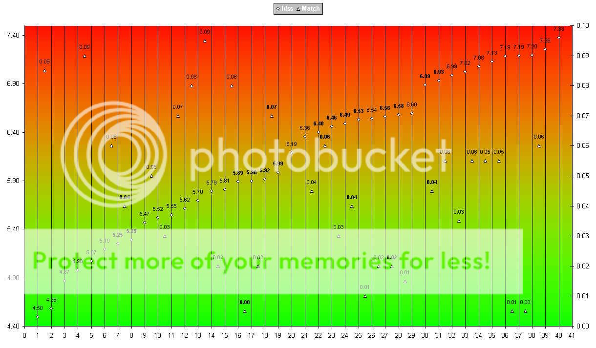
Try spending a day or more matching a large batch!
It can drive you batty...
I use a curve tracer on my stuff. Mostly because I have it and it does show up any unexpected non-linearities and bad devices (low breakdown voltage for example). It also permits you to choose a device based upon higher breakdown voltage, which in this design could be a plus depending on the B+ voltage you end up with...
_-_-bear
Do you mean between two channels??
If so, I would likely opt for a decent match between the two channels if the choice was between that and "perfect matches" IN a channel but rather different between channels.
The reason is that the values that end up being used for the biasing will be closer between channels - which at least on paper means that the characteristics of the two channels will be closer.
You have a couple of good candidates in your spreadsheet shown...
Of course, this is really getting "fine" and the amps will work ok and probably not sound audibly different using even random Jfets, although maybe NP or others have other experiences with this amp...
Try spending a day or more matching a large batch!
It can drive you batty...
I use a curve tracer on my stuff. Mostly because I have it and it does show up any unexpected non-linearities and bad devices (low breakdown voltage for example). It also permits you to choose a device based upon higher breakdown voltage, which in this design could be a plus depending on the B+ voltage you end up with...
_-_-bear
I used 2sk246 and 2sj103, but that was meant to be my secret.
Too late now.
There is a trick though to get them to work properly in the F5 circuit. Let's see if Patrick can figure it out.
Thanh or Patrick:
I would like to try 2sk246/2sj103. Would you tell me your secret ?? How to get them work properly in the F5.
Or would any one answer please ?
Thanks.
Thanh or Patrick:
I would like to try 2sk246/2sj103. Would you tell me your secret ?? How to get them work properly in the F5.
Or would any one answer please ?
Thanks.
First off, the cascode jfets need to have idss slightly greater than k170/j74.
So you need "bl" grade parts not "gr". These are not easy to find.
Now from memory you may need to increase the source and feedback resistors by a factor of 5 (or it might be 10). This may not be the optimum working point for this amp, but it aint bad either. That is about it.
Using bipolar transistors will work just as well, cviller allready has some pcbs available.
Thanh:
Thank you for your reply. I have 3 pairs of 2sk246/2sj103 and they are BL grade (not matched though). When you said .. increase the "source" and "feedback" resistors by a factor of 5, do you mean increasing R1 & R2 from 10ohm to 50ohm and R5/R7 & R6/R8 from 50ohm to 250ohm ?? Thanks.
Thank you for your reply. I have 3 pairs of 2sk246/2sj103 and they are BL grade (not matched though). When you said .. increase the "source" and "feedback" resistors by a factor of 5, do you mean increasing R1 & R2 from 10ohm to 50ohm and R5/R7 & R6/R8 from 50ohm to 250ohm ?? Thanks.
Using bipolar transistors will work just as well
Bipolars would work in Q1/Q2 position for F5? Anything to keep in mind or can we just swap in something of the right V rating and a high enough beta?
Thanh:
Thank you for your reply. I have 3 pairs of 2sk246/2sj103 and they are BL grade (not matched though). When you said .. increase the "source" and "feedback" resistors by a factor of 5, do you mean increasing R1 & R2 from 10ohm to 50ohm and R5/R7 & R6/R8 from 50ohm to 250ohm ?? Thanks.
Thanh:
Thank you for your reply. I have 3 pairs of 2sk246/2sj103 and they are BL grade (not matched though). When you said .. increase the "source" and "feedback" resistors by a factor of 5, do you mean increasing R1 & R2 from 10ohm to 50ohm and R5/R7 & R6/R8 from 50ohm to 250ohm ?? Thanks.
Yes, that is right. I think it might even be as high 100R source, and 500 feedback. I have to go over my old schematics which are on a different computer.
The cascode devices don't need to be matched but the idss needs to be higher (eg 1mA higher) than k170/j74.
So if k170/j74 have idss of 9mA then you want cascodes with idss of 10mA (even 9.5mA maybe good enough).
This looks more elegant than the bipolar method in terms of simplicity, but I feel the bipolar approach will give better absolute performance (ie measured distortion), whether it will be an audible difference I don't know because I haven't built both versions.
I think Nelson went with 10R in the source to get the absolute highest open loop gain before applying feed back, using 50R or 100R here will reduce that. Correct me Nelson If I am wrong
The aim is to get the source resistor as close to 10R as possible while keeping everthing working nicely. I may have required 100R because the idss of k246/j103 was lower than k170/j74. It was quite a while ago that I did it, I am not 100% about the reason now.
I am a trial and error kind of person, and I also have a bad memory.
Hopefully you have enough info here to troubleshoot any problems you might run into.
Once you have built it make another one with bipolar cascodes and compare.
Last edited:
Bipolars would work in Q1/Q2 position for F5? Anything to keep in mind or can we just swap in something of the right V rating and a high enough beta?
No, BJTs can not be used as a simple drop-in replacements for JFETs.
With some adjustments, a simplified schematic for F5 with BJT input would look like this:
Attachments
There is no reason to use 2SK246/2SJ103 for the frontend. Their Yfs is too low and hence you lose too much open loop gain and hence amount of feedback. And you need to increase the values of the feedback resistors, which also reduces closed loop bandwidth.
If the motivation is to be able to live with high voltage, you can just cascode the 2SK170/2SJ74s with J111/J174 (Idss about 25~30mA). This will give you something like 5V Vds on the toshiba JFETs, and it is self biasing. Simpler than using BJTs.
At least this is what I would do. Of course there are other solutions that will work as well.
Patrick
The circuit shown in #8231 has no bias on the BJTs as they see no voltage on Vbe.
You need something like an amplified diode, but my knowledge of BJT circuits is poor.
AndrewT ?
Patrick
That circuit (post #8231) has very exact bias (about 7mA) on input BJTs through R4 and R5, R14 and R16.
It's tested circuit.
If you think of Vbe what is it - voltage between base and emitter, not just base to ground.
Circlotrons and xFETs are great, but they are not all what there is - es gibt auch die anderen Dinger zu spiel mit
")
Last edited:
There is no reason to use 2SK246/2SJ103 for the frontend. Their Yfs is too low and hence you lose too much open loop gain and hence amount of feedback.
Patrick
I wasn't aware that Yfs of the cascode devices was also important. I was led to believe that the cascode device had very little affect on the rest of the circuit.
Thanks
I thought you were using them in place of the K170/J74.
Even then, as cascode, the 2SK246/2SJ103 offers too little voltage (Vds) across the K170/J74, something like 2~3V. This means that any variation in Vds due to the high effective source resistance of the cascode device under dynamic load will have an effect on Id of the gain device.
On the J111/J174 I am using, I managed to get about 4V Vds on the gain device, and the Yfs is quite a bit higher than K246/J103. So I can only suggest that you try them for a comparison.
But Juma's BJT solution is also good, nice & simple. I like it, especially when used with truely complementary MOSFETs like K1530/J201.
Sometime later in the year, I shall try a F5 with K163/J44 frontend + K2955/J554 2nd stage.
This will be a even more complementary design than K170/J74 + K1530/J201.
Patrick
Last edited:
- Home
- Amplifiers
- Pass Labs
- F5 power amplifier