my amp is biased about 1.2 A (0,57V on resistors due small heatsinks). Transformer 600VA . Output devices Vishay IRFP. Sound is excellent IMHO.
Hello,
Are you running matched prs on the outputs ? typical cost of the vishays ?
regards .
I went to bed it was night here.I read the comments.I think there is sth wrong with 100ohms feedback resistors .thank you for the answers.what is the matter ?")
The problem is that you have tried to adjust everything with just one pot. If you have 4.8 over R3 and 3.8 over R4, it means that you have Q3 running at full throttle, only limited by the fact that you have running Q4 only half turned on.
Turn P1 so that you get ~400mV over R11
Turn P2 until you have 0V dc on the output (without burning anything of course)
Check R11 and R12
Make tiny adjustments on BOTH P1 and P2 until you get 0.6V on R11 and 0V dc
umut: such a high DC offset in positive polarity means N channel (-rail) MOSFET is not turned on at the same level as the P channel (+rail) MOSFET. You have to first reduce the gate drive on positive MOSFET by turning the bias pot, then turn up the negative drive by turning that pot. Others have said so in multiple different ways. The offset will swing the other way, it will reduce and reach zero, and back down in negative direction if you do that.
If you are turning the positive pot backwards, is there a change in the offset, or is it not moving at all? You cannot leave the positive pot where it is and turn the negative pot. That increases bias on both channels.
Is the best analogy. You have to control the flow and temperature of the water by adjusting both taps (pot), sometimes it may be needed to reduce one tap (pot).
If you are turning the positive pot backwards, is there a change in the offset, or is it not moving at all? You cannot leave the positive pot where it is and turn the negative pot. That increases bias on both channels.
water faucet
Is the best analogy. You have to control the flow and temperature of the water by adjusting both taps (pot), sometimes it may be needed to reduce one tap (pot).
The problem is that you have tried to adjust everything with just one pot. If you have 4.8 over R3 and 3.8 over R4, it means that you have Q3 running at full throttle, only limited by the fact that you have running Q4 only half turned on.
Turn P1 so that you get ~400mV over R11
Turn P2 until you have 0V dc on the output (without burning anything of course)
Check R11 and R12
Make tiny adjustments on BOTH P1 and P2 until you get 0.6V on R11 and 0V dc
No no.I tried both of the pots as you say.But Bias is getting very high with only several turns.I know how to adjust it because i built it before.I got 10mv offset when i built a year ago.But now sth is wrong.I will check all the components later.thanks
Last edited:
Hello,
Are you running matched prs on the outputs ? typical cost of the vishays ?
regards .
No, they are not matched. In my country cost for one Vishay transistor - 5 USD approx.
http://www.elfa.lv/cgi-bin/index.cgi?artnr=71-001-42&lng=eng
But strange is that they sometimes sends one of the transistors with Vishy labels, but sometimes with the IR manufacturer's emblem. I usually ask them specifically for Vishy. Product price and the code is identical in both Vishay and IR in their database.
Last edited:
umut: such a high DC offset in positive polarity means N channel (-rail) MOSFET is not turned on at the same level as the P channel (+rail) MOSFET. You have to first reduce the gate drive on positive MOSFET by turning the bias pot, then turn up the negative drive by turning that pot. Others have said so in multiple different ways. The offset will swing the other way, it will reduce and reach zero, and back down in negative direction if you do that.
If you are turning the positive pot backwards, is there a change in the offset, or is it not moving at all? You cannot leave the positive pot where it is and turn the negative pot. That increases bias on both channels.
Is the best analogy. You have to control the flow and temperature of the water by adjusting both taps (pot), sometimes it may be needed to reduce one tap (pot).
Is it possible that one of my pots damaged and not working properly?Because I forgot to put r3 and r4 when i first ran the amp.Maybe current damaged pots
I don't think that would damage the pots, there's simply not enough current to do that.
And if you followed the guide and set the pots to minimum resistance, the current would not flow through the track. Also the fact that the bias is increasing (you say it is getting very hot) when you turn the other pot, means it is working for sure.
Check your rails. One other member here had some difficulties with the output adjustment, and found one rail was disconnected, setting it right fixed the amp up again. The same thing happened to me, one transistor lost connection with the board, the speaker gave a loud burp (thankfully it was fine) and the offset jumped to about 1 volt but stayed there. Restoring the connection fixed it right up.
> That's one. I can think of a couple others...
Let me make a fool of myself :
Connect the source of Q1 & Q2 on each (left or right) half together, then connect these two junctions across the two halves with a 10R resistor. The feedback resistors are then 25R and goes from output to the source junction. Non-inverting then.
According to John Curl, this "H" diff pair has very good distortion cancellation.
Patrick
Could'nt you show a little drawing, please?
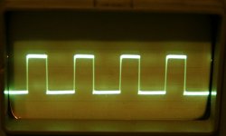
I finally connected together correctly generator and scope.
Here is a picture with a 20kHz square signal on dummy load (i try higher frequency signals also - looks good too), In addition, I connected a scope with 8 ohms speakers- and played Denon audio technical CD (with different signals etc) Even at max volume with passive preamp there is not visible clipping.
After this I conclude that my amplifier works well technically. The rest is a matter of taste.
Attachments
I finally connected together correctly generator and scope.
Here is a picture with a 20kHz square signal on dummy load (i try higher frequency signals also - looks good too), In addition, I connected a scope with 8 ohms speakers- and played Denon audio technical CD (with different signals etc) Even at max volume with passive preamp there is not visible clipping.
After this I conclude that my amplifier works well technically. The rest is a matter of taste.
Oscar , could you put up a 20 Hz Square wave , 1 watt , 10 watt etc ...
I have managed to get 2sj108 but could not get 2sk370... so instead I have picked up 2sk364. The main differences I can see from the datasheets is that 364 has higher power dissipation and higher forward transconductance... Also the 364 datasheet does not contain noise data.
Will 364 be a decent replacement for the 370?
One more thing , I have only managed to get the GR series ... I couldn't find the BL series ... will this be a problem? NP's article said BL is preferable but GR and V should also do.
I guess best way is to try and see if it works
Will 364 be a decent replacement for the 370?
One more thing , I have only managed to get the GR series ... I couldn't find the BL series ... will this be a problem? NP's article said BL is preferable but GR and V should also do.
I guess best way is to try and see if it works
The problem is that you have tried to adjust everything with just one pot. If you have 4.8 over R3 and 3.8 over R4, it means that you have Q3 running at full throttle, only limited by the fact that you have running Q4 only half turned on.
Turn P1 so that you get ~400mV over R11
Turn P2 until you have 0V dc on the output (without burning anything of course)
Check R11 and R12
Make tiny adjustments on BOTH P1 and P2 until you get 0.6V on R11 and 0V dc
I solved the problem.Trimpots were reverse polarized.now i connected reversed and it is playing well now
sound is smooth and very detailed My aluminium cooler is 50cmx10cmx5cm buckhorn.It is about 1.5 kilograms.My lab-room is too cold now and i cant guess how it will be in summer.Here in my country it reaches to 39Celcius degree.Do you think my cooler is enough for F5?I solved the problem.Trimpots were reverse polarized.now i connected reversed and it is playing well now
Post up a pic .......
maximum input voltage to clipping
I hope someone can help .
I use a promitheus DAC and connected to the F5 via a passive attenuator--Lightspeed.
At 4 V output form the DAC, there is some distortion with some disc.
It sound fine with 2 V output .
What is the maximum tolerable output from the dac ?
It sounds excellent with a total of 160000uF . Is there any advantage in increasing more capacitance in the power supply rails ?
Thanks
kp93300
I dont know the answer here but its true that 4V is higher than optimal for voltage through the resistors of the lightspeed. But you would have to have it at near zero volume to get 4V across that series resistor anyway. This probably is not your problem its just a shot in the dark. The best voltage is around 2.5V for the lowest distortion. I looked for the datasheet that showed that but havent found it.
Uriah
Uriah
- Home
- Amplifiers
- Pass Labs
- F5 power amplifier