I used 2 of his 10.080 x 7 heatsinks for a stereo set. The fins were already vertical.
I found them to be more than sufficient for my F5 which has a pretty good amount of open air around it in an air conditioned room.
I think BarredBoss might be a vendor here with a subforum.
I found them to be more than sufficient for my F5 which has a pretty good amount of open air around it in an air conditioned room.
I think BarredBoss might be a vendor here with a subforum.
Could you or anyone else on this board comment on the audible differences (improvement) between an amp using chokes versus .1 ohm resistors in the amp PS?
Yes I can,it is MUCH better. It measures better and sounds alot better than it measures. Don't take a drooling looser like compressit's word for this though.
See post 4935
what it is I see on those graphs
Temperature Coefficient = Tempco= TC
TC for a resistor is in ppm/C, unit of the Temperature Coefficient for a MOSFET is mV/degree, as in : mV change per degree.
The F5 is biased at 1.3A, you can find the Tempco at that current level from the set of curves in the graph.
TC of a single device is not interesting, the F5 output stage is not a single device but a "complementary" pair.
To compare the thermal runaway of different pairs requires determining TC for the entire output stage.
(it's when you look at the curves of the Bad Bad IRFP9240 when things become interesting)
(it's when you look at the curves of the Bad Bad IRFP9240 when things become interesting)
I sense you are being ironical
Ok, lets try it then
Please point out the FIGURE ?. we should be looking at ?
http://www.oup.com/us/pdf/microcircuits/students/mos/IRFP9240.pdf
To me it seems some curves are going opposite way of what I would expect, which confuses me
Last edited:
Figure 7 is the Vgs-Id graph.
The famous hump IRF P-channel has Zero TC at Id=2A, TC is less than 2mV/degree at a drain current of 1.3 Amp
(Zero TC doesn't happen for the FQA12P20 untill Id reaches 12 Amps, 2SJ201 even has to go beyond the graph axis limit to make ends meet)
The famous hump IRF P-channel has Zero TC at Id=2A, TC is less than 2mV/degree at a drain current of 1.3 Amp
(Zero TC doesn't happen for the FQA12P20 untill Id reaches 12 Amps, 2SJ201 even has to go beyond the graph axis limit to make ends meet)
Last edited:
Hi,
Set the bias pots to zero. On CVillers' board he has legs 2&3 together which means you turn completely counter clockwise to zero it. On Peter Daniel's board he has pins 1&2 together which means you start with the pot turned completely clockwise and bias it by turning it counter-clockwise.")
Thank you for this piece of information, should help many first fire-up
BBQs....
Russellc
Hi Russellc,
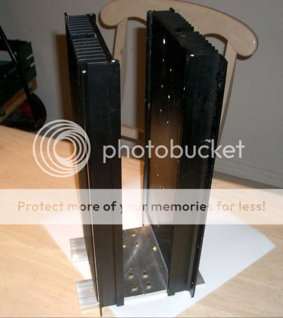
It's tough to find a case for the F5, much less one that looks like Peter Daniels'. I too liked his build and have finally put together an ugly sister (only one channel so far).
I searched eBay until I found appropriate sinks and aluminum bars from Home Depot along with a hacksaw/miter box (labor intensive). I also had to learn to drill & tap holes (not very difficult actually)
Is it running yet? Thanks for the post.
russellc
TC is less than 2mV/degree at a drain current of 1.3 Amp
(Zero TC doesn't happen for the FQA12P20 untill Id reaches 12 Amps, 2SJ201 even has to go beyond the graph axis limit to make ends meet)
I have to admit I still dont really see it clearly, but I take your word fore it
But he 150 degree and 25 ditto crosses around the point you mention
Is that what you point at, thermal instability
Nelson says its more reluctant to thermal runaway
But you seem to conclude that the Toshiba might be worth the exstra cost
That it should be considere
Thats really all I wanted to know
Thanks Jacco
Thanks Papa Nelson, now I know better why I had to be so patient to bias my F5 with Fairchild devices without termistors. In the next days I´ll have a check on the behavior of the IR devices. It is a great pleasure to look at the differences small changes can make.By the way, I don't recall mentioning that different Mosfets
have different temperature coefficients, for example the
temperature coefficient for Vgs of the Fairchild devices is
about twice that of the IR parts.
This means that temperature compensation is less necessary
for the IR parts.
Needless to say, other manufacturer's parts are likely to
vary also.
Thank you for this piece of information, should help many first fire-up
BBQs....
Russellc
Couldn't agree more, though I would say it would help to prevent BBQs...
This bit is also crucial information!This was my understanding, also, regarding the trim pots, until I fired the amp for the first time. I am using C Villers boards and the Bourns 5K trimpots. If the trimmers are turned counter-clockwise, full current will be delivered to the circuit. The trimmers must be turned clockwise to zero the current You can read the gory details Here. Fortunately, my components survived this misstep and the amp is settling in well.Hi,
Set the bias pots to zero. On CVillers' board he has legs 2&3 together which means you turn completely counter clockwise to zero it. On Peter Daniel's board he has pins 1&2 together which means you start with the pot turned completely clockwise and bias it by turning it counter-clockwise.
Attachments
Is it running yet? Thanks for the post.
russellc
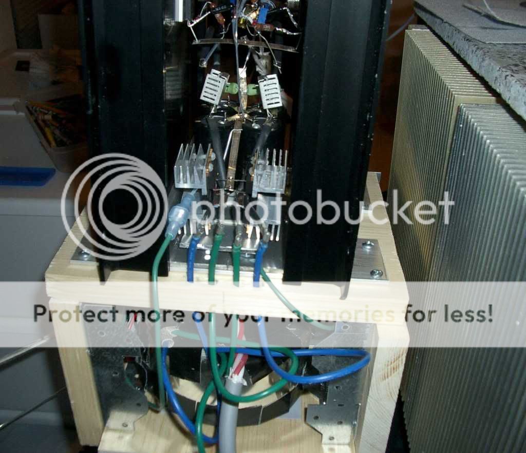
I had it running for a few days before the discussion of R1&R2 wattage ratings came up. Initially I thought I had .33w resistors there and had played it at volume so was surprised that they didn't fail. However, I rechecked and they are actually 1watt HOLCO resistors.
It's a PTP that I used for practice before I use my "better" caddock parts, and to see if I needed R9. So for those here with a Lightspeed Attenuator and F5 (I see quite a few here who frequent both threads), you can probably make it without R9. Just one less resistor in the pathway
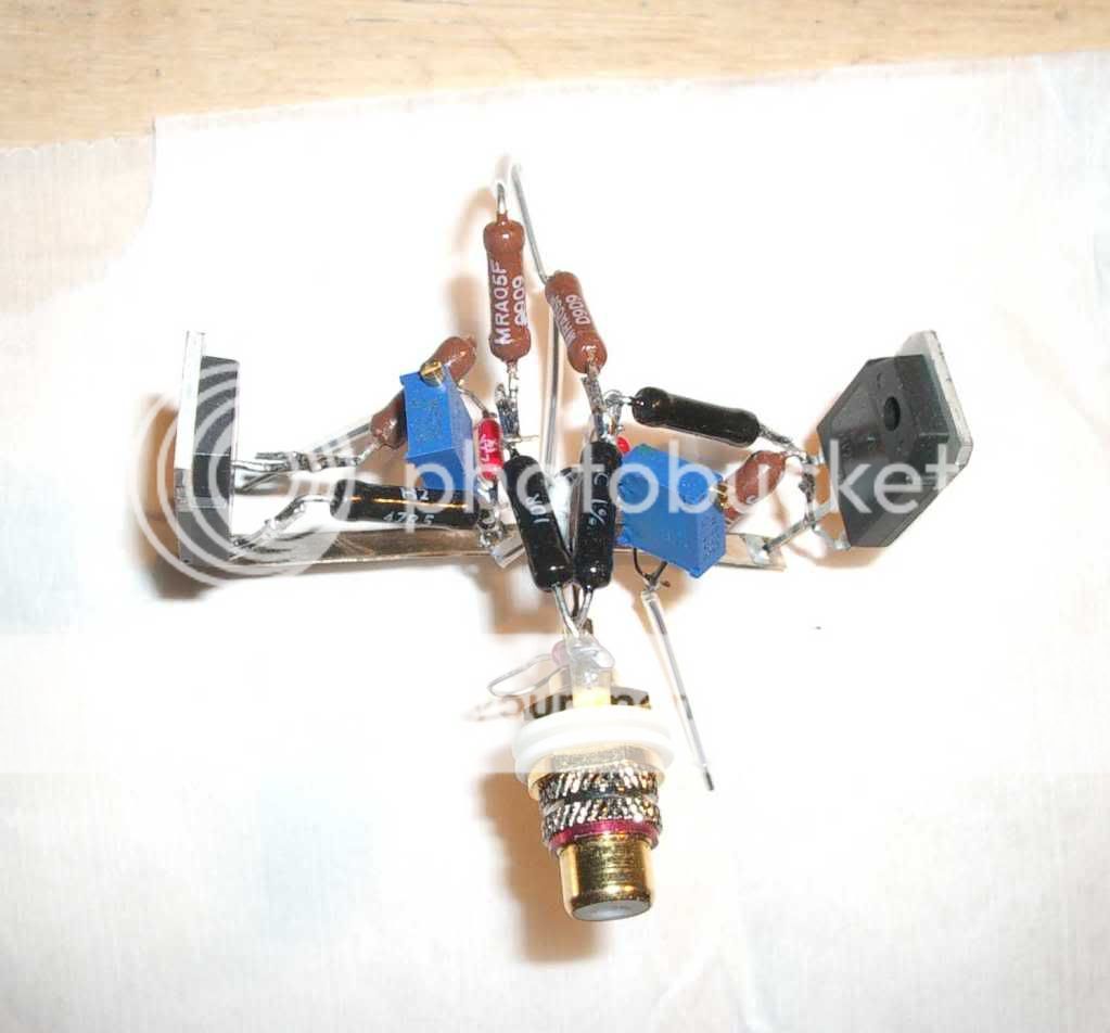
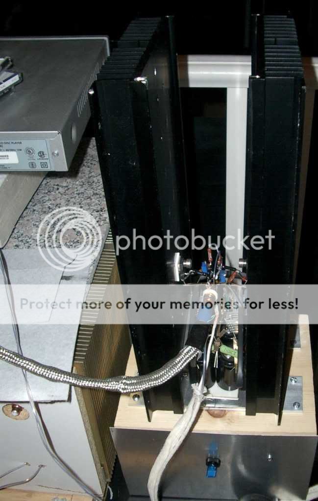
Not terribly elegant looking. None of my stuff turns out that way. More like a caveman put it together
I have PD's boards and may use them as I built it to be interchangable with his formfactor.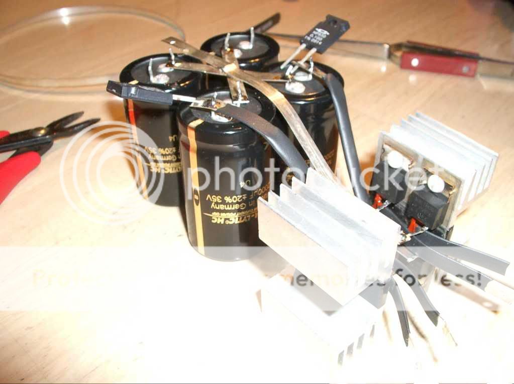
I thought why not make everything point-to-point, even the bridge diode.
So for those here with a Lightspeed Attenuator and F5 (I see quite a few here who frequent both threads), you can probably make it without R9. Just one less resistor in the pathway
According to F5 manual R9/10 are fore safety reasons to minimize any problems with parasitic problems from a connected source
You know that too, Im sure
But Im not sure its safe to be that categorical regarding the Lightspeed
I suppose it would very much depend on the individual build and setup
Or maybe even the signal source before the preamp
btw, I got my Jfets today
Attachments
Last edited:
This was my understanding, also, regarding the trim pots, until I fired the amp for the first time. I am using C Villers boards and the Bourns 5K trimpots. If the trimmers are turned counter-clockwise, full current will be delivered to the circuit. The trimmers must be turned clockwise to zero the current You can read the gory details Here. Fortunately, my components survived this misstep and the amp is settling in well.
Hi,
Here I have pins 2&3 shorted, turned completely clockwise.
Maybe I'm remembering incorrectly. I'll check when I get home from work.
According to F5 manual R9/10 are fore safety reasons to minimize any problems with parasitic problems from a connected source
You know that too, Im sure
But Im not sure its safe to be that categorical regarding the Lightspeed
I suppose it would very much depend on the individual build and setup
Or maybe even the signal source before the preamp
Hi,
I didn't know R9 if for safety. If it is I'll put it in the final build.
You're right about differing systems, so that's why I used the politicians "probably", but should have been more clear. I'm using a simple setup of CD player - LSA - F5.
You must have skipped this bit in the F5 manual:
Before applying power to the amplifier, you will want to set the values of P1 and P2 to their minimum. Verify this with an ohmmeter.
How is this done in circuit? (I've already soldered them in place.)
Russellc
Hi,
Here I have pins 2&3 shorted, turned completely clockwise.
Maybe I'm remembering incorrectly. I'll check when I get home from work.
As I have the Daniels boards, I am waiting for your response!
Russellc
Right, I just checked, to be sure
R9 is precaution against the parasitics
R10 is safety reference grounding, when no signal connected
My humble guess about R9 is that it may sound ok without R9, and you may still have some oscillation or whatever without knowing, until it some day goes down without any warning
I wouldnt mess with those
Just a guess
Heavy looking amp your building
Last edited:
- Home
- Amplifiers
- Pass Labs
- F5 power amplifier