Re: f5 mods and bias
Hi Rob,
Perhaps I'm misunderstanding things but if you change R11/R12 from .47ohm to 1ohm then shouldn't you shoot for 1.3vdc to maintain 1.3 amp bias?
rob lenk said:
yes I run 1ohm (vs .47 ohm) source resistors at .59 vdc bias at 90 degrees ferinheit
Hi Rob,
Perhaps I'm misunderstanding things but if you change R11/R12 from .47ohm to 1ohm then shouldn't you shoot for 1.3vdc to maintain 1.3 amp bias?
f5 psw with multitorroids
alazira
great question, I don't know- Bueller?, Bueller?..someone.....
labjr
no they are pieces I sourced years ago- parts express or mcm i
I think-
but they don't define their output colors
hazard a guess anyone?blue black yellow red-
seems black / blue and red / yellow=voltage
what measurement could i make to determine proper hook-up of the paralleled secondaries? When I hook it up to AC black and red have the lowest voltage,roughly 4volt, and blue and yellow show the same.
Blue/black and red/yellow both show 26.5voltsacross them- when I connect yellow to blue and red to black I also measure 26.5volts.
Andrew you suggested that the paralleled secondaries will double the VA vs independent secondaries?
no more ideas on noise and positioning of the torroids or the rectification or the cap reserve?
inquiring minds....
rob
I saw two toroids stacked in a phono preamp recently in Stereophile. I wouldn't do it but I think the magnetic fields are smaller than a conventional transformer.
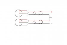
I'm not positive but I think you can parallel secondaries by observing the way which the winding goes around the core and connecting the two like pairs of ends.
I'm not positive but I think you can parallel secondaries by observing the way which the winding goes around the core and connecting the two like pairs of ends.
Nelson Pass said:When paralleling secondaries of separate transformers, better to
give each its own bridge.
Is this a good as having one large transformer?
F5 Pwr Issues Redux
Nelson-
Thanks for your thoughts
point of clairification plz-
a bridge for each section of the secondary before paralleling
or
a bridge for each transformer with the secondaries paralleled before the bridge(ie half the number of bridges)
finally if you wish to
have you heard the f5 run with paralleled amp modules?any thoughts on the idea?
thanks for your time
rob
having reread your post Nelson
perhaps I wasn't clear in my description-
I have four identical transformers- each with dual secondaries with total rating of 160 watts- the ideal at this point was to parallel the secondaries and use each transformer for a single phase with higher VA
so two transformers just create a positive voltage relative to ground and two transformers just creating a negative voltage relative to ground- these used to run 2 sets of amp modules in parallel for a higher powered stereo amp
I hope that is clear for anyone who may wish to throw in their two cents(all donations accepted)
Re: F5 Pwr Issues Redux
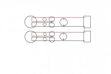
I would make a dual mono configuration with two transformers for each channel. Two secondaries from each transformer paralleled for positive and negative rails. Use two bridges for each channel like in the F5 power supply.
rob lenk said:Nelson-
Thanks for your thoughts
point of clairification plz-
a bridge for each section of the secondary before paralleling
or
a bridge for each transformer with the secondaries paralleled before the bridge(ie half the number of bridges)
finally if you wish to
have you heard the f5 run with paralleled amp modules?any thoughts on the idea?
thanks for your time
rob
having reread your post Nelson
perhaps I wasn't clear in my description-
I have four identical transformers- each with dual secondaries with total rating of 160 watts- the ideal at this point was to parallel the secondaries and use each transformer for a single phase with higher VA
so two transformers just create a positive voltage relative to ground and two transformers just creating a negative voltage relative to ground- these used to run 2 sets of amp modules in parallel for a higher powered stereo amp
I hope that is clear for anyone who may wish to throw in their two cents(all donations accepted)
I would make a dual mono configuration with two transformers for each channel. Two secondaries from each transformer paralleled for positive and negative rails. Use two bridges for each channel like in the F5 power supply.
thanh1973 said:What about dual mono with one transformer per channel.
160VA per channel is adequate.
Or do it like tinitus sketch. Make sure you wire the bridge rectifiers correctly though.
I think he needs to power four channels.

Nelson Pass said:Maybe a bridge for each secondary...
It's gonna look like Paris with all the bridges.
labjr said:
I think he needs to power four channels.
Ahh, ok then
I have misunderstood
I thought it was about a balanced amp, to get more power
Re: f5 psw with multitorroids
I am told best to keep wire to and from bridge short as they are noisy, or prone to pick up noise
Anyway, not much gain from going extreme with a two-box amp, at least not with poweramp
Unless its a problem with space
A sensible design could consist of a two-box system on top of each other, bolted together
Just be careful to have signal away from trafo
A toroid spreads out like a tellar, so it may be good "standing up" mounted at frontplate, but ofcourse depends on how your boards are placed and other layout
Two toroids flat on top of each other may be best avoided
rob lenk said:
Question:Of the three pieces in the power supply-
transformer, rectification, and capacitor resevoir, where does the noise come from?
rob
I am told best to keep wire to and from bridge short as they are noisy, or prone to pick up noise
Anyway, not much gain from going extreme with a two-box amp, at least not with poweramp
Unless its a problem with space
A sensible design could consist of a two-box system on top of each other, bolted together
Just be careful to have signal away from trafo
A toroid spreads out like a tellar, so it may be good "standing up" mounted at frontplate, but ofcourse depends on how your boards are placed and other layout
Two toroids flat on top of each other may be best avoided
fr pws redux again
LBJR
two channels output
each channel has two output modules paralleled=one channel @100w
this much is fairly straight forward as described(the hookup that is)by
NP in the F4 manual(thank you PD)
my real question is how to best use my four 160 watt 26volt dual secondary torroids.- and you are correct in that I am powering four modules- paralleled on their audio inputs and outputs
there seems to be some differences in opinion as to how to wire these four pieces together
Great reference to Paris!
I appreciate your input
rob
Re: fr pws redux again
I've never done it before. However, logically, it seems like you should use two transformers and two bridges per channel one each for the positive and negative rails. Maybe using two bridges per transformer would be better and have a separate power supply for each of the four channels.
Again, I haven't tried it. When I finally build my F5 boards, I'm probably gonna build the stock circuit and see how it sounds before I start experimenting.
rob lenk said:LBJR
my real question is how to best use my four 160 watt 26volt dual secondary torroids.- and you are correct in that I am powering four modules- paralleled on their audio inputs and outputs
there seems to be some differences in opinion as to how to wire these four pieces together
Great reference to Paris!
I appreciate your input
rob
I've never done it before. However, logically, it seems like you should use two transformers and two bridges per channel one each for the positive and negative rails. Maybe using two bridges per transformer would be better and have a separate power supply for each of the four channels.
Again, I haven't tried it. When I finally build my F5 boards, I'm probably gonna build the stock circuit and see how it sounds before I start experimenting.
Four channels and four transfos: the best arrangement is one transfo per channel and two bridges per transfo as recommends Nelson.
But 25volts AC are a lot too high except if using a regulation.
Without regulation 25 volts AC will give about 34 volts DC!!!
If you unwind secondaries to get 2x18v AC you will loose Va . You will get about bout 120VA. When voltage decrease the wire must be bigger to preserve VA rating. (less vots = more amps).
The best solution, in my opinion is to sell these transfos or to keep them for another project and to buy two 300VA 2x18volts transfos in order to obtain +/-24 volts DC.
This would bring us to one transfo and two bridges per two channels.
Staking transfos is OK.
...But may be i missed something .
bobodioulasso said:If you unwind secondaries to get 2x18v AC you will loose Va . You will get about bout 120VA. When voltage decrease the wire must be bigger to preserve VA rating. (less vots = more amps).
Now you will you need eight transformers and sixteen bridges !
From what I understand with such rather small classA theres a potential risk of amp leaving classA early when driven into low impedance
How does that relate to the fact that balanced/bridged amps "see" a normal 6ohm speaker as if it was 3ohm
Seems to me the advantage may be lost quickly, or am I missing something
Are the bias requirements different with balanced
How does that relate to the fact that balanced/bridged amps "see" a normal 6ohm speaker as if it was 3ohm
Seems to me the advantage may be lost quickly, or am I missing something
Are the bias requirements different with balanced
- Home
- Amplifiers
- Pass Labs
- F5 power amplifier