more f5 pics
#584
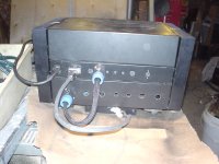
Back view before speaker or input connections-
thick cable carries raw positive and negative rectefied voltages down to the resevior on the bottom level- other cable is to bring the power and control voltage up to the fans on the middle assembly
#584
Back view before speaker or input connections-
thick cable carries raw positive and negative rectefied voltages down to the resevior on the bottom level- other cable is to bring the power and control voltage up to the fans on the middle assembly
Attachments
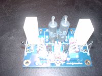
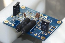
final pic- stuffed board
sorry about the focus, or lack thereof but wanted to show the tight fit will the dale resistors and the insulators(leg warmers)
also the vishay ceramic .47 r11&12 are big on the Daneils board so I added some wire jumpers to enable the nec measurements once the boards are mounted(per NP's instructions on bias setting)
Not ragging on Daneils or Tech-Diy just mentioning the adjustment that I came up with as necessitated by the confluance of the parts
Attachments
Re: f5-tech-diy kit
I know this is off topic but how did the B1 in thr Hafler dh101 chassis - I had the same idea but I haven't started yet
rob lenk said:Hi Ya Boys!
Just starting to populate my Daniels F5 boards with the parts I ordered from Tech-Diy- Both suppliers were great to deal with-had to use pay pal which I don't like but that's probably another rant for another thread.
Question- my Tech-Diy kit comes with 22k1 resistors for R21 & R22 instead of the NP specced 10k- anyone see any issues here?
A comment on the Daniels boards- they are beautiful but very tight- I think he likes the challenge- all the resistors must be vertically mounted and I would only do this, since they are tightly packed in, with lead insulators- ie teflon "leg warmers". If you haven't done this before it means cutting the tubing about an 1/8" longer than the resistor body for a gentle curving return to the board. All well and good but getting in after to measure voltage will be tough. Just a comment.
Am excited to fire up and listen and I will post pictures of both my b1 built into a Hafler DH101 and the F5 built into a Hafler DH200-the recycler twins!
have fun, be safe
rob
I know this is off topic but how did the B1 in thr Hafler dh101 chassis - I had the same idea but I haven't started yet
f5/b1 hafler rebuilds
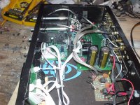
It actually works well- You can source halfway decent rca on a strip to replace the nickle orginals- move the power supply outboard- you can reuse it or upgrade and BBP has a nice little remote driven ladder volume and 4 source switcher called R2R that I used and liked
here are some pics
It actually works well- You can source halfway decent rca on a strip to replace the nickle orginals- move the power supply outboard- you can reuse it or upgrade and BBP has a nice little remote driven ladder volume and 4 source switcher called R2R that I used and liked
here are some pics
Attachments
f5/b1/hafler rebuilds
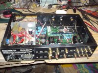
eventually I went outboard with the power supplies(5volts @ 1/2 amp for the switcher/vol and 19 volts for the B!) added a second buffer for the tape out(based on an old AA design using the NE5524) and dynamatted the floor pan- I really like the dynamat!
I rused the case work and aluminum knobs- with a few aluminum strips and some flat black paint I'm happy with the results- Just have to finish the markings on the front pannel and of course add the PassDIY logo
Hope this helps
rob
Attachments
Re: f5/b1 hafler rebuilds
Good work! My Hafler has been sitting in the closet for years and I've been trying to find a chassis for my B1 so why not. You've inspired me I think I'll give it a go
rob lenk said:It actually works well- You can source halfway decent rca on a strip to replace the nickle orginals- move the power supply outboard- you can reuse it or upgrade and BBP has a nice little remote driven ladder volume and 4 source switcher called R2R that I used and liked
here are some pics
Good work! My Hafler has been sitting in the closet for years and I've been trying to find a chassis for my B1 so why not. You've inspired me I think I'll give it a go
Re: F5-tea-bag
Lets see if we can do this. I only drink Tea and Water these days!
PM when you wan to get together. Will see if it can workout.
Mike
rob lenk said:Tea-bag
thanks for the PD info-
very generous to offer your variac- thanks again
but I've got one and will use it!
You are in Kennebunk,Yes? Perhaps we can get together for the fire-up? micro brew or vino?
Gotta love this community!
take care
rob
Lets see if we can do this. I only drink Tea and Water these days!
PM when you wan to get together. Will see if it can workout.
Mike
sorry about the focus, or lack thereof but wanted to show the tight fit will the dale resistors and the insulators(leg warmers)
I have the same boards and kits. I was also looking at those dales and wondering how to fit them. Thanks for the picture. Where did you put these jumpers? Did you just run a small wire from the lead?
Thanks
Kris
f5-test leads
sts9fan
I just tagged them underneath at the solder points and left them long enough to reach beyond the board by an inch or two- I will heat shrink the ends after measurement= little prophylactics!
Again I wish to make it clear that Peter's boards are great- just had to figure out how to fit the Tech-DIY parts and the vertical mount seemed best- Peter's suggestion with the big Dales would certainly make sinking Q1&2/Q5&6 much easier while soldering them in place-
rob
Hi,
a bridged and/or balanced arrangement with the same gain in each half will apply double the output signal voltage across the load.
That is effectively four times the power into the same load or +6dB. Subject to the usual condition that the amp can only supply +6dB if it has a theoretical zero output impedance and it's PSU similarly has a zero output impedance.
samoloko said:when start to do F5 initial setting (set the bias and dc out) the input got be connected to the gnd or no
Of course, input + and gnd (minus in) should be shorted.
samoloko said:thx for reply
It Is not pointed In manual
I guess it's one of those "common knowledge" things. To get zero output, one must assure there is zero at the input. Otherwise, if anything appear at the input, the amplifier will produce something at the output...

stein2 said:
I guess it's one of those "common knowledge" things. To get zero output, one must assure there is zero at the input. Otherwise, if anything appear at the input, the amplifier will produce something at the output...
Actually this description points out a reason why it is a good idea to do the tests without shorting the input - if there is something going on on the output with an open input, you need to fix that problem before connecting speakers.
Remember there is a shunt resistor of 100k on the input, so unless you pick up too much noise, you can assume 0V on the input.
cviller said:
Actually this description points out a reason why it is a good idea to do the tests without shorting the input - if there is something going on on the output with an open input, you need to fix that problem before connecting speakers.
Remember there is a shunt resistor of 100k on the input, so unless you pick up too much noise, you can assume 0V on the input.
some amps are sensitive to RF garbage , some not - regardless of input impedance ;
that will be step 2 .
step 1 is always with shorted input
- Home
- Amplifiers
- Pass Labs
- F5 power amplifier