Nelson Pass said:They don't have to be particularly matched.

Hello Mr Pass,
This raises the question, do you match fets/jfets in your commercial F5 amps?
cheers,
Culture
half build
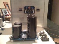
hey fellas just thought I would share my build so far. these are PD boards with tech-diy kit except for the panasonics which i had on-hand. I am almost finished with the 100+ pages of this thread trying to avoid as many mistakes as possible, but still nervous of start-up.
hey fellas just thought I would share my build so far. these are PD boards with tech-diy kit except for the panasonics which i had on-hand. I am almost finished with the 100+ pages of this thread trying to avoid as many mistakes as possible, but still nervous of start-up.
Attachments
Re: half build
Excited yes, nervous, not. Unless you really messed something up, it should be very easy, just take the basic precautions and it should go smoothly. Been there, done that, piece of cake. And I'm no expert

Pathmark said:... but still nervous of start-up.
Excited yes, nervous, not. Unless you really messed something up, it should be very easy, just take the basic precautions and it should go smoothly. Been there, done that, piece of cake. And I'm no expert
Re: Re: half build
they say " same as riding a bike ...... you never forget how ....... "
but - you must once learn how to ride .........
ya kwayzee triker .........
stein2 said:
Excited yes, nervous, not. Unless you really messed something up, it should be very easy, just take the basic precautions and it should go smoothly. Been there, done that, piece of cake. And I'm no expert
they say " same as riding a bike ...... you never forget how ....... "
but - you must once learn how to ride .........
ya kwayzee triker .........
Hi,
I've got a few questions regarding the boards I'm putting together.
R5,R6,R7,R8 - these are 100ohm 3w (which replace 50ohm 5w in tech-diy f5 kit) ( I've got to send them back )
What is R35 on the board? I guess it just dims the led. What can I stick in there?
Should I mount Q4 & Q5 now to the pcb board or wait until I have my heatsinks? (mount them on the heatsinks first?)
What part # or type are TH1 & TH2 - digikey sent me surface mounted thermistors. (I've got to send them back)
Where can I get Q1 & Q2? (any sources ?)
I've got a few questions regarding the boards I'm putting together.
R5,R6,R7,R8 - these are 100ohm 3w (which replace 50ohm 5w in tech-diy f5 kit) ( I've got to send them back
)What is R35 on the board? I guess it just dims the led. What can I stick in there?
Should I mount Q4 & Q5 now to the pcb board or wait until I have my heatsinks? (mount them on the heatsinks first?)
What part # or type are TH1 & TH2 - digikey sent me surface mounted thermistors. (I've got to send them back)
Where can I get Q1 & Q2? (any sources ?)
merlin2069er said:Hi,
I've got a few questions regarding the boards I'm putting together.
1. R5,R6,R7,R8 - these are 100ohm 3w (which replace 50ohm 5w in tech-diy f5 kit) ( I've got to send them back
2. What is R35 on the board? I guess it just dims the led. What can I stick in there?
3. Should I mount Q4 & Q5 now to the pcb board or wait until I have my heatsinks? (mount them on the heatsinks first?)
4. What part # or type are TH1 & TH2 - digikey sent me surface mounted thermistors. (I've got to send them back)
5. Where can I get Q1 & Q2? (any sources ?)
I believe most of these questions are answered in the article:
http://www.firstwatt.com/downloads/F5-om_sm-080527.pdf
or in my guide: http://viller.eu/audio/2009jan_gbf5/gbf5_guide.pdf
but here goes..
1. No problem just use the 50ohm in R5 and R8 and leave R6 and R7 unpopulated.
2. Yes you are correct. Try with 33k and adjust if you think it is either too bright or too dim.
3. Best practice is to mount them first and then solder - sometimes this is difficult, but it prevents mechanical stress in the board.
4. 4.7k NTC resistors.
5. Didn't you get those from the kit? It can be a bit difficult to find the 2sj74/2sj108, but not impossible.
cviller said:
I believe most of these questions are answered in the article:
http://www.firstwatt.com/downloads/F5-om_sm-080527.pdf
or in my guide: http://viller.eu/audio/2009jan_gbf5/gbf5_guide.pdf
but here goes..
1. No problem just use the 50ohm in R5 and R8 and leave R6 and R7 unpopulated.
2. Yes you are correct. Try with 33k and adjust if you think it is either too bright or too dim.
3. Best practice is to mount them first and then solder - sometimes this is difficult, but it prevents mechanical stress in the board.
4. 4.7k NTC resistors.
5. Didn't you get those from the kit? It can be a bit difficult to find the 2sj74/2sj108, but not impossible.
My money was refunded when I attempted to by the kits.
I've ordered everything possible from digikey. (just need those to complete the 2 channels).
Ok, I've soldered in the 50ohm 5w wire wound resistors.
Just waiting for digikey to send me a RMA so I can return the caps they messed up on, and I'll start looking around for the heatsink / case, etc...
Thanks!
merlin2069er said:
My money was refunded when I attempted to by the kits.
I've ordered everything possible from digikey. (just need those to complete the 2 channels).
Ok, I've soldered in the 50ohm 5w wire wound resistors.
Just waiting for digikey to send me a RMA so I can return the caps they messed up on, and I'll start looking around for the heatsink / case, etc...
Thanks!
You can order some here. Of course the IDSS matching will improve the more you get.
http://www.bdent.com
PS with bjt question (more PS questions)
Could y'all take a look at this and tell me why it doesn't work?
This is basically the Zen 5 power supply, with LM317/LM337 adjustable regulators and TIP33C/TIP34C BJT instead of MOSFETs. The motivation for the circuit change was to have active regulation (feedback regulation) and minimize the dropout voltage by using bjts instead of MOSFETs.
If I disconnect the PS from the amp (no load), I can adjust the regulated output (ie: it works!). When I connect the F5 amp (that I know works correctly) and use a variac to turn things up slowly, really weird things happen (like the whole circuit drawing too much current). I did turn the pots of the F5 "down", expecting to have to re-bias the amp. But that is another weird thing - even though the pots are at minimum resistance, one side of the amp will start conducting. With the variac, I do not let this go too far...
I'm going to go back to using Nelson's suggestion of the TL431 shunt regulators with the MOSFETs, but I thought I was starting to understand this stuff, and it really bothers me that this doesn't work.
Thanks for your help,
Robert
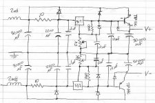
Attachments
Re: PS with bjt question (more PS questions)
What voltage are you running this at? As I see this circuit, you don't really have any gain in your regulation - you might as well just use a zener to power the base of the power transistor. Make the adjustment pin respond to the output and not some internal voltage. You can get some very good advice from the datasheet:
http://pdf1.alldatasheet.com/datasheet-pdf/view/8619/NSC/LM317.html
audiorob said:Could y'all take a look at this and tell me why it doesn't work?
This is basically the Zen 5 power supply, with LM317/LM337 adjustable regulators and TIP33C/TIP34C BJT instead of MOSFETs. The motivation for the circuit change was to have active regulation (feedback regulation) and minimize the dropout voltage by using bjts instead of MOSFETs.
If I disconnect the PS from the amp (no load), I can adjust the regulated output (ie: it works!). When I connect the F5 amp (that I know works correctly) and use a variac to turn things up slowly, really weird things happen (like the whole circuit drawing too much current). I did turn the pots of the F5 "down", expecting to have to re-bias the amp. But that is another weird thing - even though the pots are at minimum resistance, one side of the amp will start conducting. With the variac, I do not let this go too far...
I'm going to go back to using Nelson's suggestion of the TL431 shunt regulators with the MOSFETs, but I thought I was starting to understand this stuff, and it really bothers me that this doesn't work.
Thanks for your help,
Robert
What voltage are you running this at? As I see this circuit, you don't really have any gain in your regulation - you might as well just use a zener to power the base of the power transistor. Make the adjustment pin respond to the output and not some internal voltage. You can get some very good advice from the datasheet:
http://pdf1.alldatasheet.com/datasheet-pdf/view/8619/NSC/LM317.html
Re: Re: PS with bjt question (more PS questions)
Thanks for the input.
The transformer is a single secondary with a center tap. It is 22V RMS to the center tap (unloaded). After rectification and loading, the unregulated rails are about 28V.
Yes, the data sheet (and the Horowitz & Hill book) give a different circuit (with the opposite polarity devices). But I was trying to stay as close to Nelson's design as I could. And I _thought_ this would work. Which means my basic understanding of how this works is flawed or incomplete. I would like to fix that!
BTW, throw in a 221R gate resistor and a 20mA load (resistor on the regulated side to ground), and this circuit works with MOSFETs. The down side being that there is now about a 6V dropout. So what I'm wondering is why this circuit doesn't work as drawn, with bipolar transistors.
Thanks again,
Robert
cviller said:
What voltage are you running this at? As I see this circuit, you don't really have any gain in your regulation - you might as well just use a zener to power the base of the power transistor. Make the adjustment pin respond to the output and not some internal voltage. You can get some very good advice from the datasheet:
http://pdf1.alldatasheet.com/datasheet-pdf/view/8619/NSC/LM317.html
Thanks for the input.
The transformer is a single secondary with a center tap. It is 22V RMS to the center tap (unloaded). After rectification and loading, the unregulated rails are about 28V.
Yes, the data sheet (and the Horowitz & Hill book) give a different circuit (with the opposite polarity devices). But I was trying to stay as close to Nelson's design as I could. And I _thought_ this would work. Which means my basic understanding of how this works is flawed or incomplete. I would like to fix that!
BTW, throw in a 221R gate resistor and a 20mA load (resistor on the regulated side to ground), and this circuit works with MOSFETs. The down side being that there is now about a 6V dropout. So what I'm wondering is why this circuit doesn't work as drawn, with bipolar transistors.
Thanks again,
Robert
Tea-Bag said:
You can order some here. Of course the IDSS matching will improve the more you get.
http://www.bdent.com
thx for that link
what index prefer for Q1 and Q2 - BL, GR, or F
also are there difference between fairchild and vishay output jfets
Re: PS with bjt question (more PS questions)
The way you drew it, looks like that you want to use LM317 as Vref for TIP3xC ser. reg. As you noticed it won't work that way under the load - you can't make clear analogy to MOSFET here 'cause BJTs have significant base current.
But you can easily rearrange your circuit in order to make LM317 share the load with BJT - please look at the sch. in attachment (check also first sch. on page 15 in LM317 datasheet)
audiorob said:Could y'all take a look at this and tell me why it doesn't work?
The way you drew it, looks like that you want to use LM317 as Vref for TIP3xC ser. reg. As you noticed it won't work that way under the load - you can't make clear analogy to MOSFET here 'cause BJTs have significant base current.
But you can easily rearrange your circuit in order to make LM317 share the load with BJT - please look at the sch. in attachment (check also first sch. on page 15 in LM317 datasheet)
Attachments
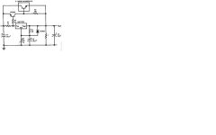
Attached schematic in previous post shouldn't be taken for granted - it's not mine, nor I tried it (AndrewT looked at it more carefully and concluded that it's flawed), it can only roughly demonstrate the idea of LM317 sharing the load with pass transistor.
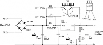
This is working schematic (from LM317 datasheet):
This is working schematic (from LM317 datasheet):
Attachments
amp-guy said:Not to to muddy the waters, but from the National Semiconductor linear databook
Hmmm having trouble attaching file say's it is to big? but its only 10k
looks like I just posted the same circuit. I have built this one a number of times. The other possibility is to just parallel up a number of 317's just like you would add output transistors in an amp.
- Home
- Amplifiers
- Pass Labs
- F5 power amplifier