Re: Re: Finished my F5
Jose',
I haven't had enough listening to compare to F4's yet, but my first reaction is the F5 has amazing transparency to small details yet doesn't beat you over the head with them. Not so much a toobey sort of sound, so for some a little syrup (peanut butter?) might be needed to feel better. Overall a very nice amp for such a small investment
Tom
I just bought a .080" perforated steel plate ($8 for 12x14" piece) from a local Metal Supermarket store. I used it on the F4's and F5 and just a few holes or gaps in the base promote nice convection. I leave a gap between the face plate and base to let air in and it's a nice safe spot for openings in the case. It isn't really stiff enough to set anything on top of, but I'd never do that anyway for these amps so it's not a problem.dhole said:Nice work on the amp.What is ther mesh made from on the top of your amp ? Looks like a good option for ventilation and economy.
dave
Jose',
I haven't had enough listening to compare to F4's yet, but my first reaction is the F5 has amazing transparency to small details yet doesn't beat you over the head with them. Not so much a toobey sort of sound, so for some a little syrup (peanut butter?) might be needed to feel better. Overall a very nice amp for such a small investment
Tom
Well guys, my F5 still ain't right. I thought I had it fairly ok, was reading .5V across R11, had 25mV on the outputs, but I connected a set of inputs (just plugged them in) and the bias went down (had the meter still connected). Then I hooked up a speaker (old) and theres a high pitch whine and a good level of hiss through it.
I wonder is that oscillation? I do have the mosfets mounting on wires, but I have a 47r right on pin1 as advised back up the thread.
Fran
I wonder is that oscillation? I do have the mosfets mounting on wires, but I have a 47r right on pin1 as advised back up the thread.
Fran
I haven't had enough listening to compare to F4's yet, but my first reaction is the F5 has amazing transparency to small details yet doesn't beat you over the head with them. Not so much a toobey sort of sound, so for some a little syrup (peanut butter?) might be needed to feel better. Overall a very nice amp for such a small investment
Ok thanks a lot Tom. I´m waiting for the F5's parts.
woodturner-fran said:Well guys, my F5 still ain't right. I thought I had it fairly ok, was reading .5V across R11, had 25mV on the outputs, but I connected a set of inputs (just plugged them in) and the bias went down (had the meter still connected). Then I hooked up a speaker (old) and theres a high pitch whine and a good level of hiss through it.
I wonder is that oscillation? I do have the mosfets mounting on wires, but I have a 47r right on pin1 as advised back up the thread.
Fran
is it source - connected to F5 - offset free ?
did you set offset with shorted inputs ( that's must ) ?
Thanks Zen,
no, I did not short the inputs. Will do that and try. No source was actually connected, all I did was plug in the interconnects, other end not actually connected at all.
So just to rehash.... both pots at zero. I turn up P1 until I see say, 50mV across R11. Then adjust P2 to bring offset at speaker terminals back to zero. Then bring up P1 again, allow to settle, adjust P2 again.
I do have that OK, don't I? So if I went for say, 50mV, then 150mV and so on that would be ok wouldn't it?
Fran
woodturner-fran said:Thanks Zen,
no, I did not short the inputs. Will do that and try. No source was actually connected, all I did was plug in the interconnects, other end not actually connected at all.
So just to rehash.... both pots at zero. I turn up P1 until I see say, 50mV across R11. Then adjust P2 to bring offset at speaker terminals back to zero. Then bring up P1 again, allow to settle, adjust P2 again.
I do have that OK, don't I? So if I went for say, 50mV, then 150mV and so on that would be ok wouldn't it?
Fran
Fran - it's completelly irrelevant with which pot you'll start - both have same function - biasing one side ;
when both sides are biased ( roughly in ballpark of wanted Iq ) same , then you'll have zero offset - as result of equal currents through halves .
anyway - seems that you didn't do your homework .....
name of the file on Papa's First Watt is "F5-om_sm-080527.pdf "
partial text is :
Initial Adjustment
Before applying power to the amplifi er, you will want to set the values of P1 and P2 to their minimum. Verify this with an
ohmmeter. When it comes times to “fi re” up the amp fi rst time, if you have a Variac, use it, fusing the AC line to the amplifi er
with a 1A fast blow fuse. Turn the Variac up slowly, and if you haven’t popped the fuse, then go ahead and confi rm the rail
voltages to the channels.
Each channel does not need to be attached to a load in order to adjust it. If the only load you have is the loudspeaker, I
would advise against using it during adjustment. For each channel you will be adjusting P1 and P2 alternately in order to
achieve 0 volts DC at the output and .59 volts across R11 and R12. Each time you adjust P1 you will probably have to go
back and adjust P2 again, and so I recommend adjusting the pots in half-measures, alternately setting the pots half-way to
their voltage goals and measuring the DC values. Unless there is something very wrong, when the output is at 0 V DC, the
values across R11 and R12 will be equal.
In spite of the thermal compensation in the circuit, you should assume that there will be drift as the heat sink temperature
rises, and you will need to readjust the values over the course of an hour or two. Usually it is best to start out bias
adjustment low, at maybe 0.4 mV across R11 and R12 until the amp is warmed up a bit.
You should be able to get the output DC offset down to 10 mV or so, and I would consider 50 mV the highest acceptable
fi gure for this amplifi er when warmed up. After the amplifi er has been operated for a few weeks, it is a good idea to check
and adjust the offset again after the parts have been burned in.
btw - having connected open cable on any gain stage is begging for trouble , especially when stage is "suspectible"
 ..... ie. with high input impedance ....
I know that text well.... have it right beside me at the bench.
Didn't know about the shorted inputs.. then this is really the first SS amp I've built - I've only assembled a mini aleph before that someone else had soldered together. Tube work and phonostages though I have done.
I'm normally better than this....honest! I thought it would be easier than this!
I do some more later and report back.
fran
I did all my adjustements with nothing connected to the amp and inputs not shorted, in my setup it didn't make any difference.
I started with trimmers set halfway, that produced approx 1V drop on source resistors.
If you install trimmers according to pcb footprint, turning screws clockwise will reduce the bias.
Initially, I had 3 voltmeters conected to all 3 test points, but later only two: one on either source resistor the other on the output.
Set the offset to zero first by using either of the trimmers. After that, turn both trimmers same way, either clockwise or counterclockwise to lower the bias or to increase it.
Ok, my experience so far is that both are at zero... you need to bring both up a few turns to get any reading. I think what I'll do is start all the way clockwise (ie zero) and then turn both back up say 5 turns. I think the bourns pots are 20 turn AFAIK. See what I get and report back.
Fran
Fran
F5 oscillation
I think it's in Nelsons' article that he states, input wires should not be
near the outputs or feedback will cause oscillation. Make sure internal wiring conforms to that and short the inputs to bias.
edit:::
A caveat is in order here – this is a very wide band amplifi er with a high input impedance. In order to prevent the output
voltage from bleeding back to the input at very high frequencies (thus making a fi ne power oscillator), keep the input and
output cables separate, and don’t externally connect the speaker ground to the input ground. Good ground shielding on the
input cables is important, and caution is called for in using Litz and other specially low inductance / high capacitance cables.
I have not seen a specifi c example of a problem, but historically it is to be expected when an amplifi er’s bandwidth exceeds
200 KHz. If the amp makes funny noises, runs extra hot, or blows fuses, this might be an indicator of such an issue.:::
woodturner-fran said:Then I hooked up a speaker (old) and theres a high pitch whine and a good level of hiss through it.
I wonder is that oscillation? I do have the mosfets mounting on wires, but I have a 47r right on pin1 as advised back up the thread.
Fran
I think it's in Nelsons' article that he states, input wires should not be
near the outputs or feedback will cause oscillation. Make sure internal wiring conforms to that and short the inputs to bias.
edit:::
A caveat is in order here – this is a very wide band amplifi er with a high input impedance. In order to prevent the output
voltage from bleeding back to the input at very high frequencies (thus making a fi ne power oscillator), keep the input and
output cables separate, and don’t externally connect the speaker ground to the input ground. Good ground shielding on the
input cables is important, and caution is called for in using Litz and other specially low inductance / high capacitance cables.
I have not seen a specifi c example of a problem, but historically it is to be expected when an amplifi er’s bandwidth exceeds
200 KHz. If the amp makes funny noises, runs extra hot, or blows fuses, this might be an indicator of such an issue.:::
woodturner-fran said:Ok, my experience so far is that both are at zero... you need to bring both up a few turns to get any reading. I think what I'll do is start all the way clockwise (ie zero) and then turn both back up say 5 turns. I think the bourns pots are 20 turn AFAIK. See what I get and report back.
Fran
I had to go many turns before the voltage across R11 and R12 would do anything, then it actually is fairly steady (not jumpy) to set at this point up to 500mv or so, then had to do more fidling over time to get it to stick at .6v and <10mv offset. Mine does not drift much. Once it's sub <.05v, I let it warm up for a few hours to Willie Nelson from Laptop connection to cheap bench speakers. Then did more setting for it. I will adjust it agian once it warms up in a chassis.
I did the same thing without problems. Note, as ZM said, these are both bias settings for each half, not one bias and one offset. Once I got the 20t pots halfway, just alternate slight adjustments on either one to get it up to .59-.60V and small offset of < 10mV or so. After 3 hours mine only moved about 1-2mV.Tea-Bag said:
I had to go many turns before the voltage across R11 and R12 would do anything, then it actually is fairly steady (not jumpy) to set at this point up to 500mv or so, then had to do more fidling over time to get it to stick at .6v and <10mv offset. Mine does not drift much. Once it's sub <.05v, I let it warm up for a few hours to Willie Nelson from Laptop connection to cheap bench speakers. Then did more setting for it. I will adjust it agian once it warms up in a chassis.
ok..... so I should be able then to adjust P1 upwards and see a voltage develop across R11. R12 stays at zero? Then bring up P2 to match and get the same voltage across R12. At that point I should have zero offset, right?
On a side issue. There are 2 other things here I need to watch. One is the PS setup, dual mono but with all the grounds tied together at the speaker terminals. Second thing is that all my grounds are brought together here, thats PS, input and output. in a star...
I wonder if I would now be better to run shielded twisted pair from inputs to boards, then separate twisted pair to the outputs. Run GND from PS to the boards rather than the "star" at the speaker terminals.
*************
I'll get back out tonight after the kids hit the hay and investigate more. I really appreciate all of your patience in this......
Fran
I think you're going to need to bring both pots up together gently, enough to turn on both output transistors.
You can look at my pictures for grounds, though I am using CViller's boards. Even on Peter's F4 boards I brought a ground wire (not necessarily shielded) from each floating RCA connector to the SG input on each PC board. Speaker grounds and DC power grounds are all tied together as star, and there is a thermistor between that DC ground to chassis ground (the way Nelson does it). Chassis metal ground is tied directly to the mains ground at the IEC connector.
You can look at my pictures for grounds, though I am using CViller's boards. Even on Peter's F4 boards I brought a ground wire (not necessarily shielded) from each floating RCA connector to the SG input on each PC board. Speaker grounds and DC power grounds are all tied together as star, and there is a thermistor between that DC ground to chassis ground (the way Nelson does it). Chassis metal ground is tied directly to the mains ground at the IEC connector.
Well I was like this: 
But now I'm like this:
but also like this:
Yeah, I'm a gobshite. Officially.
On Peters boards there are 2 set of through holes for mounting R5-8. Well, I had mine stuck in so that the 2 legs were in the "same" track. So essentially there were no R5-8 as the amp saw it.
Now I have rock solid 590mV bias and 5mV offset and if I played with that a bit more I can go to 0 offset. On one channel I have a little imbalance on R11/R12, of the order of about 15mV. After things settle a while I'll go back and look at that again.
So it onwards now. One question remains though. Should I refit all the current limiting stuff or not bother? What do you guys think? Would leaving it out be a danger to speakers?
Thank you all so much for the help.... I knew something was wrong when the bias was off like that. Just had to stare at it a bit longer.
Fran
I doubt 15mV is much difference to worry about.
The current limiting will just protect you from near dead short kind of stuff. The way I look at it, it's only 2 inexpensive non-matched complementary Mosfets and 0.47r's, so if I cook one or two while doing something stupid with the output wires they're easy enough to replace.
The current limiting will just protect you from near dead short kind of stuff. The way I look at it, it's only 2 inexpensive non-matched complementary Mosfets and 0.47r's, so if I cook one or two while doing something stupid with the output wires they're easy enough to replace.
mmm and I note that Peter seemed to indicate that the amp sounded a bit better without the current limiting bits. In any case, I'm gonna leave them out for now until I get her all cased up and fitted. I still need to do some tidying up inside, things like connecting the GND to chassis earth, power LEDS and such niceties. I got some nice binding posts and neutrik RCAs in teh mail today and I might just go back and swap them in instead of what I have there.
Again, my heartfelt thanks to all who helped me out here.
Fran
Again, my heartfelt thanks to all who helped me out here.
Fran
Fran,woodturner-fran said:mmm and I note that Peter seemed to indicate that the amp sounded a bit better without the current limiting bits. In any case, I'm gonna leave them out for now until I get her all cased up and fitted. I still need to do some tidying up inside, things like connecting the GND to chassis earth, power LEDS and such niceties. I got some nice binding posts and neutrik RCAs in teh mail today and I might just go back and swap them in instead of what I have there.
Again, my heartfelt thanks to all who helped me out here.
Fran
Glad to hear it's finally singing properly. Now go listen to some music
 and you won't even care about some cheezy connectors.
Tom
Re: ebay pcbs
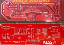
I don't know about the pcb - it looks fairly nice, but I haven't looked into it in detail. It does however seem to violate the PASS logo.
Any particular reason why you want to buy those boards instead of those offered at the two group buys?
juluska said:What do you think about that pcbs that sold on ebay?
I's worth a try to build that kits?
I don't know about the pcb - it looks fairly nice, but I haven't looked into it in detail. It does however seem to violate the PASS logo.
Any particular reason why you want to buy those boards instead of those offered at the two group buys?
- Home
- Amplifiers
- Pass Labs
- F5 power amplifier