Peter Daniel said:
Why not using IR Mosfets for now and when Faichilds become available again, replace them. Chances are, you won't need to replace them at all, as they work perfectly fine in my amp")
You could also use the Toshiba sk21530/2sj102. Am I right in thinking that we'd need to see ~2.7V across R3/R4 (instead of the 4.2V for the IR or Fairchild parts) in order to bias the Toshibas to 1.3A?
-j
jacco vermeulen said:If you bridge two amplifiers, maximum output level goes up but Class A output will remain the same.
100W in Class A is twice the bias level of 25W, twice the Class A bias current requires 2 F5's in parallel. (same same story as the F4)
4 times 60W =240W dissipation for 100W/8 in A, 200W/4 in AB.
Jacco,
I've been dwelling on this and don't understand.
So I wired up 2 F4's in mono, but I am not sure how they deliver 100watts, assuming 15-25W is the normal class A operation per board.
I would assume that they operate class A at 2X the normal by running them in Mono mode, but that would only bring me to 50watts for F4.
I understand the F5 can be wired in the same way, and would assume a monoamp effectively doubles it's working bias and class A output by using both boards.
I still don't understand for the F4 - what the leap in wattage is all about. I assume that the F4 even runs in class AB at some point.
So the F4 works much as a parallel SE tube amp maybe?
Can someone explain it to my thick mind? I am lost on difference between 'parallel' and bridged modes, and what we are doing with F4 and F5 when running as such.

Tea-Bag said:
Jacco,
I've been dwelling on this and don't understand.
.....
without counting tiny worms of exact details "how to" ....... :
with paralleling - output voltage is same , current doubled
with bridging - current is same , voltage doubled
in ideal world - you'll have 4x power in bridged mode .......
in any case - limits are real voltage and current limits of amp itself ......
you must know what's plain amp's channel capable ....... then you'll know what benefits are in other possible configurations .....
read F4 paper again ..... and again ..... and again .....
kwayzee white beard-ed/hair-ed already scribbled all needed
edit:
luckily - I'm not Jaccovitty .......

the rule for bridging is simply: double the power into double the load impedance.
Take a 50W into 4r0 amplifier. Maximum voltage is 20Vpk. Maximum current is 5Apk.
Now bridge a pair of these. We get 100W into 8r0. Maximum voltage is 40Vpk. Maximum current is 5Apk.
Note that maximum voltage has doubled and that maximum current is the same.
If your 25W of ClassA power into 4ohms is doubled to 50W of ClassA into 8ohms, then both the amplifiers set ups deliver the same maximum current and therefore if one remains in ClassA then so does the other.
I've just put together my F5 using the Peter Daniels boards. I have a problem.
The set up is dual mono, and the rail voltages all are correct. However I can't seem to bias the channels. So I have my +/- 24V going into the boards. From the pass manual, I'm supposed to measure the voltage across R11 and at the same time adjust P1. I do this going back and forth between R11/P1 and R12/P2. So the pass manual states that the end point should be 0.59V across R11 and R12. In the subsequent paragraph, he says that its a good idea to start low, maybe 0.4mV across R11/R12.
Theres a big difference between 0.4mV and 0.59V?
Anyway, I don't seem to be able to set the bias at all. I measure across R11 or R12 and all I get is 0 to 2.4mV. no matter how I adjust P1/P2. If I do a check on voltages at the speaker output, I get about 40mV most of the time, but if I watch as I adjust P1/P2 very suddenly I get the rail voltage to the speaker outputs.
Don't see what I have wrong. Need to take some photos too.
Any suggestions gratefully received!
Fran
Yeah, I know thats the most likely case. Anyway, I'll look at it again tomorrow and verify that all the right parts are fitted. The fact that both boards are doing the same thing means that I've made a systematic error somewhere. I'll double check everything and maybe reflow solder connections even though they all went pretty sweet.
More tomorrow.
Fran
More tomorrow.
Fran
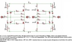
Bridging Power
Bridging two F5's across the same load (say nominally 8 ohms) as a single F5 both doubles the voltage swing and the current, all else being equal. P=IV, so 2 x 2 = 4. A bridged F5 pair should produce at least 100W, but it will come out of Class A operation at a percentage of it's output rating....probably ~ 50-75W. The big IF is the current limit of the amplifier, which in NP's circuit is nominally 10A. Driving an 8 ohm load, each side will conduct about 2.5A and together put about 30V across the load.....at which point they will go into AB mode.
The ultimate limit of AB mode is probably set by something else in this circuit, but when I get mine built I will have my buddy Zaw test it on his HP bench and I'll tell you when it clips.....knowing NP's bullet-proof design approach I'm betting about 120 watts into 8 ohms. Perfect match for a set of Vandersteen Quatros or 5A's, and the first watt will still be sweeeeeeett Class A "quantum triode."
Matched Fairchilds
I still have some matched Fairchilds left that I can let go, but only as sets of 4 (2 matched FQA19N20C and 2 matched FQA12P20).
Matching is single point. Matching details pls see European GB thread.
http://www.diyaudio.com/forums/showthread.php?s=&postid=1495444#post1495444
Patrick
I still have some matched Fairchilds left that I can let go, but only as sets of 4 (2 matched FQA19N20C and 2 matched FQA12P20).
Matching is single point. Matching details pls see European GB thread.
http://www.diyaudio.com/forums/showthread.php?s=&postid=1495444#post1495444
Patrick
Toshibas
> You could also use the Toshiba 2SK1530/2SJ201.
But they are much more expensive than IRF and Fairchild.
If you want true complementary, I have not seen better.
Measurements posted in this thread before.
http://www.diyaudio.com/forums/showthread.php?s=&postid=1507044&highlight=#post1507044
> Am I right in thinking that we'd need to see ~2.7V across R3/R4 (instead of the 4.2V for the IR or Fairchild parts) in order to bias the Toshibas to 1.3A?
Yes, so you need to adapt the circuit (e.g. lower bias for the JFETs). I used 6mA Idss, which are unfortunately not easy to get. You can of course also lower the resistor value at the drain of the JFETs.
Patrick
> i 'm trying with all of these output mosfets..fairchild sounds more clear..treble is better..and 2sk1530 is stable and good..
That depends on how you change the circuit for the Toshiba's to make the most of their complmentary characteristics, and to compensate for their lower Vgs.
As mentioned, those who need Fairchilds but could not wait for jackinnj can contact me by PM.
Patrick
That depends on how you change the circuit for the Toshiba's to make the most of their complmentary characteristics, and to compensate for their lower Vgs.
As mentioned, those who need Fairchilds but could not wait for jackinnj can contact me by PM.
Patrick
> but these mosfets are expensive..can we try irf540 /9540 ?they are much cheaper...but maybe the circuit must be redesigned
Maybe you should just stick to the Fairchilds and the original Pass circuit.
You would not get the best from the Toshiba's unless you change the circuit to balance the open loop gain of the top half to the bottom half.
As to FETs being expensive, I wonder what % they cost compared to your finished amp with proper housings, heatsinks, power supplies, connectors, .......
Patrick
I installed Q2 backwards. Never saw it despte checking.
So I turned them around but neither channel works. Could some kind soul let me know whats likely to be dead and what I need to replace?
Anyone any ideas?
If I just order more of Q1 and Q2... would Q5 and Q6 be affected by my mistake?
Fran
- Home
- Amplifiers
- Pass Labs
- F5 power amplifier