Re: f5 pcb
Always, always you want the gate stopper resistors mounted as close as possible to the gates of the MOSFETs.
umut1001 said:hi..my friend draw this for me..i wanna build f5 amp to 50cm of heatsink..for good cooling we decided to put the mosfets far eachother..what do you think about this?thanks
Always, always you want the gate stopper resistors mounted as close as possible to the gates of the MOSFETs.
umut1001 said:yes true.. i know shorter is better but for better cooling mosfets must be far eachother..its dilemma.i dont know what to do..
Copper just might do the trick for you.
Magura
")
umut1001 said:yes true.. i know shorter is better but for better cooling mosfets must be far eachother..its dilemma.i dont know what to do..
It really isn't an option -- if the distance from the resistor to the MOSFET gate is too long the device can break into oscillation.
Thought I'd post another few pics. I sprayed my chassis tonight so while the paint was drying I finished another few bits of prep work. There is still a little chassis work to do like feet and the front panel. However I think the soldering on the boards and PS is just about done.
The alu panel was an internal panel inside the case I am using for the amp. Made it very handy to mount the transformers.
I amp going dual mono with this one so hopefully it will pay dividends. More I do the more I believe that the PS is critical to nearly everything. Just as important as the "circuit".
Like mentioned above, I am mounting the mosfets directly to the heatsinks and running some wire back to the PCB. Hope it will work out ok. The wires are about 3-4" long, will probably be a bit shorter when I mount properly to the PCB on the chassis.
If anyone sees anything wrong in all this, let me know!!!!
Fran
An externally hosted image should be here but it was not working when we last tested it.
The alu panel was an internal panel inside the case I am using for the amp. Made it very handy to mount the transformers.
An externally hosted image should be here but it was not working when we last tested it.
I amp going dual mono with this one so hopefully it will pay dividends. More I do the more I believe that the PS is critical to nearly everything. Just as important as the "circuit".
Like mentioned above, I am mounting the mosfets directly to the heatsinks and running some wire back to the PCB. Hope it will work out ok. The wires are about 3-4" long, will probably be a bit shorter when I mount properly to the PCB on the chassis.
An externally hosted image should be here but it was not working when we last tested it.
If anyone sees anything wrong in all this, let me know!!!!
Fran
Well I did ask, but the answer I got was "any heatsink will do". The diodes are the big 3 pin ones MUR3020. The heatsinks are about 3" high, 4" wide and about 11/2" deep fins on 1/4" plate. If they get too hot I'll add another pair of them and separate out so that only 4 diodes are on each heatsink. There are ventilation holes right above and below them in the casework for improved airflow. If I have to add a fan I have some to hand and will use the same circuit for controlling the speed as I did in the mini-aleph (thanks again to Nelson).
The mosfets are going on 12" long by 6" high by 2" deep heatsinks. Mosfets spread a little for cooling. I do hope they work out ok. I'll know in a few days when I fire it up.
I decided to do the chassis work first this time. I hate it normally but I kinda made a rule for me. If I want to listen to it inside in teh house, it has to look at least semi ok. Pass the WAF test and be safe enough for my 3 kids to be near!
Fran
No... to be honest I just put them on the PCB. That was following the advice here back up the thread that running wires upto 12" long to the mosfets should be AOK. And that was a quote from Nelson. (these are the 47R R13 adn R14, right?)
If its wrong, or if I picked up the advice wrong.... I can change it.
Anyone have an opinion on this?
Fran
If its wrong, or if I picked up the advice wrong.... I can change it.
Anyone have an opinion on this?
Fran
Sorry Fran,
My mistake -- thought those black heatsinks were for the o/p fets, not the diodes!!
And yes, best to add those resistors on the legs of the power fets.
Also, check out the old article about diode snubbers on the Haggerman site- they work very well and simple to try.
My mistake -- thought those black heatsinks were for the o/p fets, not the diodes!!
And yes, best to add those resistors on the legs of the power fets.
Also, check out the old article about diode snubbers on the Haggerman site- they work very well and simple to try.
labjr said:Are you soldering the grid-stopper resistors to the MOSFETs ?
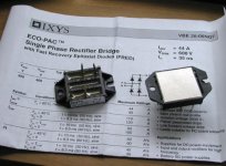
Both in F3 and now in F5 I'm using IXYS. Bought them years ago through the forum, but I guess Percy carries them too.
I intend to also try discrete diodes.
Attachments
Peter Daniel said:
Both in F3 and now in F5 I'm using IXYS. Bought them years ago through the forum, but I guess Percy carries them too.
I intend to also try discrete diodes.
Those aren't the diodes with the overshoot problem are they?
Thanks
- Home
- Amplifiers
- Pass Labs
- F5 power amplifier