MRupp said:
... the risk of a catastrophic failure with the output swinging to full rail voltage.
I hardly see such catastrophic risk. The amp limits the peak current at 10A. In addition, it has the "foldback" function in case that the voltage is high between the rail and the middle point.
Cheers,
>>
") <<
<<I admit that I do not understand this "foldback" function and I would not mind an explanation - thank you My concern is that my speakers would not survive too many volts DC at the output and replacing even a single driver unit - most likely the mid-range driver - would be VERY expensive. With a F4 that has 3 FETs in parallel I would feel comfortable even without DC protection, but with just one FET I would not ...
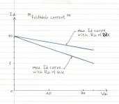
My concern is that my speakers would not survive too many volts DC at the output and replacing even a single driver unit - most likely the mid-range driver - would be VERY expensive. With a F4 that has 3 FETs in parallel I would feel comfortable even without DC protection, but with just one FET I would not ...The power dissipation of the output mosfet could be expressed as W=IV, where I= current through the mosfet and V= voltage across the mosfet. When the mosfet sees maximum current (limited to 10A) and the maximum voltage (abt. 20V/output short/just in case) at the same time, the power dissipation will reach to the maximum, which might cause a damage of the mosfet. To avoid this situation, when the mosfet sees the maximum voltage, the "foldback" current system reduces the current flowing through it, and reduces the power dissipation.
I understand that the "foldback" is provided to protect the output mosfets. If there is no problem with the output mosfets, the amp would work normal without giving users any problem.
Nevertheless, if you feel uncomfortable, I recommend you to go with the comfortable >> <<
<<
Cheers,
I understand that the "foldback" is provided to protect the output mosfets. If there is no problem with the output mosfets, the amp would work normal without giving users any problem.
Nevertheless, if you feel uncomfortable, I recommend you to go with the comfortable >>
<<Cheers,
MRupp said:With a F4 that has 3 FETs in parallel I would feel comfortable even without DC protection, but with just one FET I would not ...
Odd reasoning, if one of three blows you'd have serious problems as well.
Babo's story is half right, R21/R22 will trigger the BJT's at a lower Vds level.
Take 9A output current in a continuous 1.5 Ohm load, for example.
(some folks buy LSP's with input transformers.
 )
)Here is my estimation of the foldback current. The maximum Id values are reverse proposional to the Vds values. Of course, the foldback happens at any Vds. I do not know whether I'm right with my estimation. I am just doing my best
Cheers,
>><<
Cheers,
>>
<<Attachments
Odd reasoning, if one of three blows you'd have serious problems as well.
My assumption was that no, 2 out of 3 can still carry the current from the other half of the circuit or at most would show a fraction of the total rail voltage as DC, so less of a problem.
 Also, I would run at lower bias per FET therefore lower the chip temparature and failure rate.
This is off course disregarding the downside of higher capacitance which might impact the bandwidth and sound, as might the lower chip temparature per FET (I am not sure about the latter) ...
(some folks buy LSP's with input transformers. )
Que ? Never seen any - passive - but then I have not seen that much (my subwoofers have an input transformer since they are active).
I'm waiting on some f4/f5 pcb's from pd so I thought i'd get on and design the enclosure for the amp. Seeing as the f4/f5 use the same power supply (which could also be used for various other amps) I thought i'd make the amp and power supply in to different enclosures.
The only problem with this is getting all the grounds sorted. The mains ground will obviously be connected to the power supply chassis. I'll have a 3-pole outlet on the power supply and matching inlet on the amp. Now, do I connect the power supply GND to the mains GND in the power supply (via thermistor) and to the chassis of the amp?
I'll try and knock up a quick diagram if I can find my mouse, I can't stand laptop pads for drawing!
phresh said:The only problem with this is getting all the grounds sorted.
Mains ground goes directly to chasis.
Signal ground -> NTC -> chasis (same point on chasis!)
Re: toshiba mos
Yes, certainly. R3 and R4 smaller as Toshiba mosfets have Vgs ~1/2 of IR & Fc counterparts. Be careful not to overbias Toshibas, P1 and P2 can help you.
umut1001 said:hi..do i have to change any resistor value on the circuit if i wanna use 2sk1530/sj201 ? thanks
Yes, certainly. R3 and R4 smaller as Toshiba mosfets have Vgs ~1/2 of IR & Fc counterparts. Be careful not to overbias Toshibas, P1 and P2 can help you.
Seperate case earthing problems
Phresh, To do the earthing properly, there are a lot more connections than you'd think - can reduce it as you want, depending on results. It makes an enormous difference to the amp's performance if you go to some trouble to get it "right". +/- /0 (Rails) X 2 = 6 wires (from Power caps - the 2nd ones in a C-R-C or C-L-C system) 0V for each speaker (- ve) return to Power Caps = 2 wires 0V for input (signal) shield = 2 wires (maybe 1 with resistors) to P/Supply Central Earth 0V for amp chassis to P/Supply Case Earth (ground connection, RF reduction, etc)[6 + 2 + 2 + 1 = 11 total) Have I left any out? If you use a regulator in the amp case, you will want 2 more seperate 0V links to the Central Earth point. Inside your P/Supply, the Central Earth (Star) point is usually at the Power Caps -ve (or near to it) and all the "earth wires" go to this - but not always, unfortunately. Central Earth point is often "raised" from the ground connection via a resistor, diode or, here, a CL60 device. Now, just how well all these earth connections really work depends a lot on how you actually pull them together and this has been an extraordinary point of argument over the years, so I'll not add to it here - many of us have very different ideas about "how good is enough" and this directly effects how many wires you want to use for this seperate box. I remember AndrewT has a rather good diagram some time ago that very clearly showed the different links between supply and amp - perhaps, if this is still available ....?
Phresh, To do the earthing properly, there are a lot more connections than you'd think - can reduce it as you want, depending on results. It makes an enormous difference to the amp's performance if you go to some trouble to get it "right". +/- /0 (Rails) X 2 = 6 wires (from Power caps - the 2nd ones in a C-R-C or C-L-C system) 0V for each speaker (- ve) return to Power Caps = 2 wires 0V for input (signal) shield = 2 wires (maybe 1 with resistors) to P/Supply Central Earth 0V for amp chassis to P/Supply Case Earth (ground connection, RF reduction, etc)[6 + 2 + 2 + 1 = 11 total) Have I left any out? If you use a regulator in the amp case, you will want 2 more seperate 0V links to the Central Earth point. Inside your P/Supply, the Central Earth (Star) point is usually at the Power Caps -ve (or near to it) and all the "earth wires" go to this - but not always, unfortunately. Central Earth point is often "raised" from the ground connection via a resistor, diode or, here, a CL60 device. Now, just how well all these earth connections really work depends a lot on how you actually pull them together and this has been an extraordinary point of argument over the years, so I'll not add to it here - many of us have very different ideas about "how good is enough" and this directly effects how many wires you want to use for this seperate box. I remember AndrewT has a rather good diagram some time ago that very clearly showed the different links between supply and amp - perhaps, if this is still available ....?
Sorry -
To do the Earthing properly, there are a lot more connections than you'd think - you can reduce them as you want, depending on the results and it makes an enormous difference to the amp's performance if you go to some trouble to get it "right"
+/-/0v Rails X 2 = 6 wires. Speaker -ve returns = 2 wires. 0V for inputs, shields, etc = 2 wires. 0V for amp case to P/Supply case (gnd, RF rection, etc). Total = 11 wires
If you use a regulator in the amp case, add another 2 X 0V wires.
Have I left any out?
How well all these earth connections work depends on how they all come together, and this has been the source of considerable argument over the years - there really isn't any one "correct" way and many of us have very different ideas about "how much is enough" - it gets quite expensive, too.
Perhaps if AndrewT reads this thread and could post up the very clear diagram about Power supply circulating currents, earth loops, etc, that he did awhile ago .....?
That's a bit better - I'm not fond of these small size Gyration keyboards - a real pain in the ....
Cheers, i'd completely forgotten about the grounding thread so managed to find it with a search.
My biggest issue was whether to connect the signal grounds to the chassis in the amp along with the power supply grounds. From a diagram in the aformentioned grounding thread it seems best to pass all grounds back to the power supply and connect them there and then pass the mains earth to the amp chassis. If that makes sense anyway!
This did make me think of how Naim build their equipment where all grounds are passed back to the power supply.
about feedback resistors
hi..today i bought some pieces for f5 amp..for feedback i have noname 100ohms metaloxide and 100ohms hitano wirewound resistors..which one is preferable?amp has big input empedance and someone says it causes oscillation..maybe wirewound ones cancels the oscillation?
hi..today i bought some pieces for f5 amp..for feedback i have noname 100ohms metaloxide and 100ohms hitano wirewound resistors..which one is preferable?amp has big input empedance and someone says it causes oscillation..maybe wirewound ones cancels the oscillation?
Yeah, Phresh,
The grounding ideas can be quite confusing - I think of it as.... any wire that contains power current (rails, speaker returns, potential chassis earth currents, etc) should be seperate from any signal wire, and their shields - high probability of "ground loops".
Now, if you take this a step further, you seperate the power rails (supply) and amp speaker wires (output) - this is just better power distribution and returns - obvious, really.
This results in the 3 seperate and distinct groups/types of earth wiring, okay?
When you have a seperate p/supply case, add another one that keeps both cases tied directly to the mains earth connection, not the "star"earth on the supply, with everything else.
The same thing applies with preamps, Xovers, etc, even tho there isn't large currents - the "ground plane" needs to be much cleaner.
The idea of using balanced line level signals can be quite useful but also produces it's own problems and even more connections!
What do you guys think about this heatsink?
farnell heatsink link
Fins 40mm (1 1/2") with 10mm (3/8") thick base plate, 100mm (4") high and 300mm (12") long
Its rated at 0.4 degC/w which I know is a wee bit high but the next one up is $$$ more. Its also a very reasonable size to fit in my rack and it won't be as tight a fit between the shelves...
Is it reasonable to mount Q3 and Q4 out to the very tips of the their legs to spread them out as far as possible on the heatsink (12" long) or will that cause problems (using the Peter Daniel boards)?
Fran
You will be operating the heatsinks at a lower temperature difference level than what is used to measure their thermal resistance factor.
Means the heatsinks will be less efficient in your application, you need a bigger one to obtain the same C/W value.
Secondly, the thermal resistance factor of a heatsink also depends on the altitude it is used at.
Way up the mountain, the heatsink thermal factor will drop significantly again because of lower air pressure, some 20% lower efficiency at an altitude of 10.000 ft compared to sea level.
- Home
- Amplifiers
- Pass Labs
- F5 power amplifier