having got it from tech-diy, I had assumed so, never tested them.
.
i checked all the JFETs before they go out.
and i don't do F5 kits anymore -- althought i use between 4 and 8 of them at any given point of time.
Jack, this has been ordered a while ago (a year or so if I remember correctly), it's just quite recently the amp came to life (as time permitted), and even more recently I managed to take these measurements.
Thanks for the kit and even more so for the PCBs - it's certainly not taken for granted.
Would you have any version of why I have such a difference between channels?
Thanks,
Alex.
Thanks for the kit and even more so for the PCBs - it's certainly not taken for granted.
Would you have any version of why I have such a difference between channels?
Thanks,
Alex.
Last edited:
Did you test each component prior to using it? have you played about with topology? i dont know if the picture in post 11 is recent? a couple of comments on it. the transformer at the front seems to be missing the top cap fixings (can affect behaviour), bottom cap board looks way to close to the transformer can you raise it higher.
think about the magnetic fields going on inside the chassis and try to balance them out
it may be worth taking everything out the case and laying it spread out on the table to test, to rule out topology, if it behaves out of the case you may need to rethink the layout. maybe try mounting the transformers vertically one at the front and one at the back, un-stacking the cap boards and fixing them to the bottom of the case mount the rectifiers on the front and back panels, run the signal cables in the top of the cabinet and the power along the bottom.
think about the magnetic fields going on inside the chassis and try to balance them out
An externally hosted image should be here but it was not working when we last tested it.
it may be worth taking everything out the case and laying it spread out on the table to test, to rule out topology, if it behaves out of the case you may need to rethink the layout. maybe try mounting the transformers vertically one at the front and one at the back, un-stacking the cap boards and fixing them to the bottom of the case mount the rectifiers on the front and back panels, run the signal cables in the top of the cabinet and the power along the bottom.
Hi Ash,
I have tested the resistors (had to swap some), but did not test the j/mosfets (not sure how).
I also tested both PSUs before connecting to the boards - they are ~26.5V (or ~24.5V +/-0.5V when loaded). The PSUs are irrelevant in my issue, as I found swap them does not swap the channels behaviours, i.e. it's PCB-bound (having all the resistors checked and matched at ~1%, does it mean the transistors are misbehaving?)
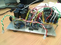
Layout - yes, a lot of relocations were made here. I expected more influence from the transformers positioning, but there was not! Transformers on sides, stacked transformers, transformers apart, caps away from the transformers, one transformer/one cap bank, one transformer/two cap banks, main boards away from everything (20cm from transformers/caps) - tried all these permutation.
Surprisingly the boards were not influenced by the proximity to transformers in my small enclosure (it is 21cm(w) x 30cm(d) x 21cm(h)). Here is its latest state:
I have tested the resistors (had to swap some), but did not test the j/mosfets (not sure how).
I also tested both PSUs before connecting to the boards - they are ~26.5V (or ~24.5V +/-0.5V when loaded). The PSUs are irrelevant in my issue, as I found swap them does not swap the channels behaviours, i.e. it's PCB-bound (having all the resistors checked and matched at ~1%, does it mean the transistors are misbehaving?)
Layout - yes, a lot of relocations were made here. I expected more influence from the transformers positioning, but there was not! Transformers on sides, stacked transformers, transformers apart, caps away from the transformers, one transformer/one cap bank, one transformer/two cap banks, main boards away from everything (20cm from transformers/caps) - tried all these permutation.
Surprisingly the boards were not influenced by the proximity to transformers in my small enclosure (it is 21cm(w) x 30cm(d) x 21cm(h)). Here is its latest state:
Attachments
Just trying to get back on track with it. Started with resetting the bias yesterday. So far one channel (after about 1hr warm up) is perfectly steady at 858-862mV with offset at 2mV.
The other channel (with the high frequency loss) is jumping all around 750-930mV (changes within 1-2 seconds!), offset is not bad, but drifting -5+10mV (not as rapidly as the bias).
Any debug ideas - what voltages at what points to measure?
I suspect the input jfets - how to diagnose if they are bad? Don't have them spare, so would like to confirm if possible before reordering new.
- Status
- This old topic is closed. If you want to reopen this topic, contact a moderator using the "Report Post" button.