With the 2SK170/2SJ74 is becoming unobtainium, for circuits like F5 power amp or F5 headamp, it is very difficult for most to source components.
A few days ago, John Curl posted a series of schematics for a Simple Power Amp.
http://www.diyaudio.com/forums/the-...owtorch-preamplifier-ii-1921.html#post5182531
http://www.diyaudio.com/forums/the-...owtorch-preamplifier-ii-1921.html#post5182618
One of them is using FETs as output devices.
http://www.diyaudio.com/forums/the-...owtorch-preamplifier-ii-1922.html#post5183160
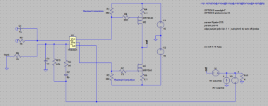
Now if you replace the opamp, R23 and C4 with a pair of JFETs, it is almost identical to the F5-HA schematics.
So you can actually build a F5-HA without the JFETs.
If you use OPA604 which will take +/-24V, and scale things up, you can even do it for a power amp.
")
Patrick
A few days ago, John Curl posted a series of schematics for a Simple Power Amp.
http://www.diyaudio.com/forums/the-...owtorch-preamplifier-ii-1921.html#post5182531
http://www.diyaudio.com/forums/the-...owtorch-preamplifier-ii-1921.html#post5182618
One of them is using FETs as output devices.
http://www.diyaudio.com/forums/the-...owtorch-preamplifier-ii-1922.html#post5183160
Now if you replace the opamp, R23 and C4 with a pair of JFETs, it is almost identical to the F5-HA schematics.
So you can actually build a F5-HA without the JFETs.
If you use OPA604 which will take +/-24V, and scale things up, you can even do it for a power amp.
Patrick
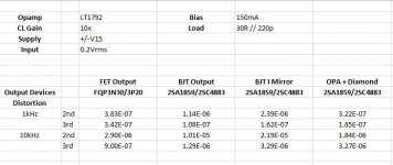
Simulations
There were in addition some suggestions for improvement (against thermal run-away), and a reference to benchmark against.
http://www.diyaudio.com/forums/the-...owtorch-preamplifier-ii-1923.html#post5184115
http://www.diyaudio.com/forums/the-...owtorch-preamplifier-ii-1922.html#post5183506
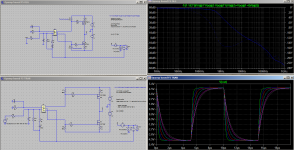
Just for fun, we simulated them all in Spice, using the LT1792 opamp model that emulates the supply current correctly. (Not all opamp models do.) You can find the .asc files below :
http://www.diyaudio.com/forums/the-...owtorch-preamplifier-ii-1922.html#post5183506
http://www.diyaudio.com/forums/the-...owtorch-preamplifier-ii-1922.html#post5183370
http://www.diyaudio.com/forums/the-...owtorch-preamplifier-ii-1922.html#post5183568
http://www.diyaudio.com/forums/the-...owtorch-preamplifier-ii-1922.html#post5183596
A summary of the simulation results is also attached.
Patrick
.
There were in addition some suggestions for improvement (against thermal run-away), and a reference to benchmark against.
http://www.diyaudio.com/forums/the-...owtorch-preamplifier-ii-1923.html#post5184115
http://www.diyaudio.com/forums/the-...owtorch-preamplifier-ii-1922.html#post5183506
Just for fun, we simulated them all in Spice, using the LT1792 opamp model that emulates the supply current correctly. (Not all opamp models do.) You can find the .asc files below :
http://www.diyaudio.com/forums/the-...owtorch-preamplifier-ii-1922.html#post5183506
http://www.diyaudio.com/forums/the-...owtorch-preamplifier-ii-1922.html#post5183370
http://www.diyaudio.com/forums/the-...owtorch-preamplifier-ii-1922.html#post5183568
http://www.diyaudio.com/forums/the-...owtorch-preamplifier-ii-1922.html#post5183596
A summary of the simulation results is also attached.
Patrick
.
Attachments
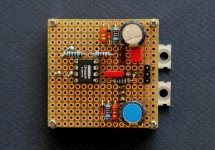
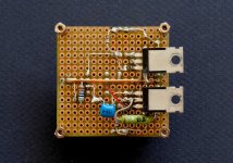
But simulation is not reality, right ?
So just for fun, I built a pair this weekend to find out.
They were done in less than a day including taming oscillations.
The OPA604 has an idle current of 5.2mA as measured.
So the FET bias resistors have to be changed to 1.1k for FQP3N30 & FQP3P20 at 150mA.
Even with bandwidth limiting to 100kHz in the feedback network, the circuit still needs a Zobel to be stable.
Pretty aggressive at 1.8R-1µ, but the circuit values may not be optimal.
For example, changing R23 to 1k will help stability and allow less bandwidth limiting.
With about 100dB negative feedback, it will of course sound different to the original F5.
But still fun to build, and very low cost.
I actually just used parts lying in my drawer.
Patrick
.
Attachments
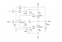
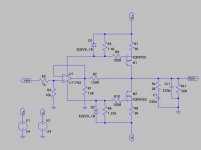
But this has way too much open loop gain (~120dB) and hence negative feedback.
So can we reduce the gain to about the same level as a pair of 2SK170/2SJ74 ?
Yes We Can.
And we can even make it simpler.
R1 sets the transconductance of the opamp to 66mS.
And R2/R1 determine the closed loop gain (11x).
C2 and R2//R1 determines the closed loop bandwidth, now at 1.5MHz.
And THD is about the same level as the original F5-HA.
This will sound good.
Patrick
.
Attachments
Hi, Patrick!
While you have embarked on a vicious road of feedback there are no other way than bear your's burden and take full advantage of deep feedback.
Try high-GBW opamps like AD8067, LM7171 or THS4021.
Some thougths about external compensation to curb those beasts can be taken from old Jim Karki's article:
http://www.ti.com/lit/an/slyt174/slyt174.pdf
PS.
Why noninverting config? Just simulate CMRR.
Last edited:
For the purpose of this particular application here, the opamp should have the following characteristics :
1) JFET input
2) Low noise (<<10nV/sqrtHz)
3) Max. supply voltage +/-18V or more
4) Unity gain stable
5) Idle current 4~8mA.
AD8067 is limited on supply voltage.
LM7171 has to have a minimum gain of 2.
And THS4021 is bipolar input.
But many other JFET opamps will satisfy those requirements, like e.g. OPA627.
I used OPA604 because it can take+/-24V, and I have them in the drawer; that's all.
Patrick
Last edited:
Patrick,
I don't know how you generate the links to forum posts, but they don't work for me.
The link to the schematic with FET outputs I find to be
John Curl's Blowtorch preamplifier part II
can you confirm I picked the right one?
I don't know how you generate the links to forum posts, but they don't work for me.
The link to the schematic with FET outputs I find to be
John Curl's Blowtorch preamplifier part II
can you confirm I picked the right one?
Yes, you did.
And the problem apparently arises because I set the post number per page to 50.
It used to work without problems for years.
Patrick
Put your mouse cursor over the number of the post for which you need the link. Then "Copy link location" and you got it, you just need to paste it now. Example using this way, your post #10 :
F5 Headamp with Opamps ?
All the links I posted work just fine for me.
So it is not that I copied the wrong location.
It has to do with the pages numbers in addition to the post number.
But Elfishi has found the right one anyhow.
So just read the posts a few pages after that.
Or set your post / page to 50 temporary.
Patrick
So it is not that I copied the wrong location.
It has to do with the pages numbers in addition to the post number.
But Elfishi has found the right one anyhow.
So just read the posts a few pages after that.
Or set your post / page to 50 temporary.
Patrick
JFET input
Why you claim as needed picoAmpere input currents and bias current?
There are only special demands for PCB cleaning.
JFET input useful for photodiode applications with insufficient current drive.
There we always have previous DAC with some kind of output buffer, so sufficient current drive at both inputs.
Low noise (<<10nV/sqrtHz)
Always needed, mostly as reference for achieving low THD.
Max. supply voltage +/-18V or more
One BJT + one zener + resistor will solve the problem with easy.
Or just put zener in series it will eat some voltage.
Unity gain stable
I can't agree.
Idle current 4~8mA.
Yeah. Let's try.
Attached images shows schematic with OLG and Transition response.
Thermal compensation not drawn.
C2 (Cfb) allows some step response correction, example shown for 100 kHz square wave. With 4pF it will have 1 MHz -3 dB bandwidth, with 18 pF around of 200 kHz. Unity gain frequency changes from 4 MHz to ~800 kHz.
Attachments
I am sure we'll find many other combinations, especially with various compensation schemes.
My purpose was to illustrate a way to replace the input JFETs of the F5-HA, without changing its basic topology.
For me, the schematics in post #7 comes closest.
Of course you can also replace the JFETs with BJTs, as Juma showed right at the beginning of the F5 Headamp thread a few year back.
Would be good to see someone take the plunge and build something.
Cheers,
Patrick

Stixx has built 14 before his final destination.
So you still have some way (years) to go.
DIY - Original-Ton
And building is also part of the fun, not just the listening afterwards.
Patrick
So you still have some way (years) to go.
DIY - Original-Ton
And building is also part of the fun, not just the listening afterwards.
Patrick
- Status
- This old topic is closed. If you want to reopen this topic, contact a moderator using the "Report Post" button.
- Home
- Amplifiers
- Pass Labs
- F5 Headamp with Opamps ?