7 pairs each biased at 286mA for a total of 2A using 24V rails or 7 pairs each biased at 186mA for a total of 1.3A with 40V rails.
What ever sounds best.
4 prs would work for me using 30V rails ....
Having said that, I did a little Pspice over the weekend and found the Low Z F5 version (19V rails and Dual Outputs) to be producing an OLG of about 233 vs. 333 for the std. F5. Source Rs of about 0R22 would raise the gain to about 255.
I'm going to procede with the build as in the schematic above.
Using Cvillier style boards ?
OMG, just think, someone could build active line-arrays with like 20 F5 channels each side and trazillion Watts dissipation.
Stop, what am i saying ?
First that P guy lures me to this forum with his Monster routine.
And now i'm sucked into F5 transformer talk, on a thread of that guy who used to be at another thread.
Woosh, gone with the wind.
(well, out through the back door into the dumpster-array alley, actually)
Stop, what am i saying ?
First that P guy lures me to this forum with his Monster routine.
And now i'm sucked into F5 transformer talk, on a thread of that guy who used to be at another thread.
Woosh, gone with the wind.
(well, out through the back door into the dumpster-array alley, actually)
Sure, CViller bds designed to be a std. circuit, and/or a cascoded circuit, and/or a dual output circuit. Whatever version that is? There is a picture on maybe your 3rd page.
Juma's suggested reading is good. But, did you notice it was centered around driving the capacitance of complimentary source followers? A Circuit like the F4?
The major consideration when driving the capacitance of a common source circuit involves the output cpacitance being multiplied by your voltage gain. For example: If the ouput stage gain is 10 multiply that * Coss for the C value you will really have to drive. Also consider how much the Coss changes with Vds.
And Jacco, I didn't say I was driving a 1000s or even 100s of watts, 25-50W is all i'll ever want with over 100db efficiency.
Last edited:
The OLG is load impedance dependent.
Patrick
When I replied to you before Patrick, I may not have understood where you were coming from. Yes, as you say gain is dependant on output R. It is to easy to be thinking my version and comparing it to a std. F5 driving 8 ohms.
Truth is, in this regard, into 2 ohms is a big deal? The small mods I'm making may or may not change the sound to any great degree. But, a std F5 driving 8 ohms is well known, I stated OLG to be about 333 from my simming. I stated I found more like 233 in the version I'm workin on now, driving 2 ohms!
An F5 driving 2 ohms has an OLG of 83 @1kHz.
I think the point Juma and Nelson are making is that the current requirement to drive 3 pairs compared to 1 pair is not necessarily 3 times as much. In fact it is less. This applies to both common source and common drain.
At least that is what simulations show. Thanks everyone for this discussion. I definitely had one of those forehead slapping moments here.
At least that is what simulations show. Thanks everyone for this discussion. I definitely had one of those forehead slapping moments here.
Several years ago at this forum, someone was kind enough to thoroughly explain the charge/discharge routine to me.
As a bonus, i was informed that it also took Mr E. Borbely quite a while before he slapped his forehead.
(hey there, one could build an array of Mini F5's, not necessarily 20)
Duh, what's happening, i'm back at this thread again, starting to get that Groundhog sensation.
Woosh.
As a bonus, i was informed that it also took Mr E. Borbely quite a while before he slapped his forehead.
(hey there, one could build an array of Mini F5's, not necessarily 20)
Duh, what's happening, i'm back at this thread again, starting to get that Groundhog sensation.
Woosh.
Last edited:
No don't even suggest such things. I am sure Zen Mod will remember that one next time I say that I am dumber than him.
Seriously though this was actually an enlightening moment for me. I was actually close to discovering this several times in the past but kept ignoring the thoughts.
Too many bloody ideas kept getting in the way.
"Steve is also an ideas man. That's why Dad calls him the Ideas Man. He has lots of ideas." - The castle
You guys have to get this movie before I ruin it for everyone.

And you slap yourself and wish someone else did?Problem in your case, someone else does the slapping.

...I was slapped by Mr. Insomnia itself (G. Rollins)...
He's gone dude. who's Mr Insomnia himself now?
someone else ?
Hardly.
I spend all of my time trying to recollect why i slapped myself.
And when i do remember, i have to slap myself again.
Next morning, the very 1st thought i have is : Why did i slap myself ?
But that's another story, at least i think it is, not sure.
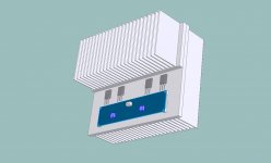
I've been busy and sick and busy but, I have some news on my high curent F5 project. I have some HeatSink USA 10.08" profile, 8" (200mm) sections that I tested for dissapation and temp rise. I used one like you see in the picture in post #23 mounted with 4 IRFP244s. I set up an adjustable current source with 1 ohm source resistors and a BC550 driving the gates. I used Kerafoil pads from Zhoufang on the transistors. I'm thinking I would like to have enough capacity in my sinks to dissapate 125W. effectively, the equivalent of 2 F5s.
The Sink was supported 3" above the table on the outer fins only, allowing for generous convective airflow on all sides. With room temp about 20C I adjusted the current for 1.3A/device with 24V D-S and let them sit for a while. After whaiting for hours, stabalization did not really take long, it was stable after the first hour. Device case temeratures rose to about 80C. The H.S. temp 1/2" from the device was about 70C. At the top of the H.S. the temp was almost 60C.
Although this is doable, I would really like to have more wiggle room. 60C at the H.S. outer extremes is a little hotter than I'ld like. I would also be happier if I could experiment with higher currents meaning, I need more H.S. I have some ideas towards improving things that I think will accomplish that.
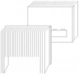
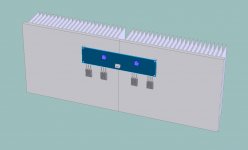
If you want to go that way, to make the inside extra heatsink, I suggest cutting one the size of the main hs in half through the bandsaw (almost the way you show, but all the way across -- no waste, right?) and mounting it flush with the top of the main hs. You will need good ventilation through the bottom panel. Then turn the pcb or mount the outputs so they're are as close to the center of the assy as possible.
Andersonix, I think I see what your your saying. There may also be issues of flatness in the 2 baseplates that require gap pad or gobs of Arctic Silver 5 or what ever to effectively make up for the lack of flatness/gaps. I could even use Arctic Silver epoxy and glue them together but, I am affraid of the end to end flatness, expansion of aluminium and maybe future use of my sink material. Although, I have used A.S. Thermal Epoxy, it's never been permanent for me. I've only used it to glue on thermal couples not for 80 insq of surface? Peices would aleviate much of that worry. I do have extra material to wack up though. I'm also conserned with making it look arteeestic and pretty, oh yea, WAF... I would be putting the In/Outs/+Gnd- on a plate across the ground away fins in the back and the PWR Supply in a seperate chasis in this case. One giant Mono Block of heat sink Mono Block would be cool. 
Last edited:
- Status
- This old topic is closed. If you want to reopen this topic, contact a moderator using the "Report Post" button.
- Home
- Amplifiers
- Pass Labs
- F5 For Low Z Loads ?