imagine some idiot shoveling input signal greater than F4 rails
diodes are working then ?
OK. I'll leave them out.
I'll see what else I can strip out of it. Hahahaha
maybe output mosfets too ?
or just skip on source resistors

Yeah I am gonna change the mosfets over to Lateral Mosfets.
Thinking of running it without source resistors with the Laterals (have slight negative temp coefficient above 500mA)
Last edited:
I just noticed this circuit, which shows paralleled 220uF caps and paralleled 0.47 source resistors.
http://www.diyaudio.com/forums/imag...cumentation/P-F4-1V20/P-F4-1V20-schematic.pdf
F-4 clone boards (2 PCBs, makes 2 channels; Rev 2.0) - Power Amplifiers - Circuit Boards
Has it been decided 0.23 Ohms and 440uF is best?
No comments are made about it and there is no room on the board to parallel these parts.
Anyone know what the history is about this schematic?
The parallel parts are just to accommodate the larger/smaller caps and axial vs caddock resistors - nothing exciting new here I am afraid.
OK thanks.
Makes sense now.
I've just completed placing the caps and source resistors.
The schematic seems to show two 0R47 resistors & 2 220uF caps!
So, I've soldered 0R22 Futaba metal plate resistors and 1,000uF caps.
Will I have trouble? More importantly, will this negatively affect
the sonics of this amp?
I just noticed this circuit, which shows paralleled 220uF caps and paralleled 0.47 source resistors.
http://www.diyaudio.com/forums/image...-schematic.pdf
F-4 clone boards (2 PCBs, makes 2 channels; Rev 2.0) - Power Amplifiers - Circuit Boards
Has it been decided 0.23 Ohms and 440uF is best?
No comments are made about it and there is no room on the board to parallel these parts.
Anyone know what the history is about this schematic?
__________________
schematic made with purpose of allowing two different pinout/cases/form factors on pcb, for those caps and resistors
then it's published without cleaning
use 220u and 0R47 , as per Papa's
though , if you squeeze 470uF there , who cares
OK then, what's the worst that can happen, if using 0R22 resistors on the source outputs? Lower output impedance? What is the purpose of these resistors, current balancing of mosfets?
1) Make it less critical to match components (load/current sharing)What is the purpose of these resistors, current balancing of mosfets?
2) Help linearise the device
3) Reduce thermal runaway
If you already have the amp ready to turn on. You may as well turn it on an keep an eye on the bias across each pair. I am also curious to see how low you can go with the source resistors with irfp240/9240
Last edited:
the size of the source resistor will be governed by the closeness of the current match . Having said that I would go with .22 ohm and not spend more time on a small thing . of your 3 statement 1. The reason for the resistor. 2. Not that much . 3. Mosfet are not BYTs thermal runaway is not there .1) Make it less critical to match components (load/current sharing)
2) Help linearise the device
3) Reduce thermal runaway
If you already have the amp ready to turn on. You may as well turn it on an keep an eye on the bias across each pair. I am also curious to see how low you can go with the source resistors with irfp240/9240
the size of the source resistor will be governed by the closeness of the current match . Having said that I would go with .22 ohm and not spend more time on a small thing . of your 3 statement 1. The reason for the resistor. 2. Not that much . 3. Mosfet are not BYTs thermal runaway is not there .
Thanks Zen Mod, Triodethom & 2 picoDumbs for your responses.
I will leave the 0R22s in, the mosfets were matched by diyaudio member h_a.
Attachments
the size of the source resistor will be governed by the closeness of the current match . Having said that I would go with .22 ohm and not spend more time on a small thing . of your 3 statement 1. The reason for the resistor. 2. Not that much . 3. Mosfet are not BYTs thermal runaway is not there .
The first part of what you said is really just another way of saying what I said at point one (it's already implied).
The point about thermally running away. IRFP240 are not lateral mosfets. They have a positive temperature coefficient. If you're heatsinks are rated for 100Watts to keep the mosfets in the SOA (say bias of 2A total on F4) and if the mosfets go from a total bias of 2Amps (0.67A each) to 4Amps then good buy mosfets this scenario can easily happen with irfp240 devices. You do need to be patient and careful when setting the bias with these devices.
Last edited:
Thanks Zen Mod, Triodethom & 2 picoDumbs for your responses.
I will leave the 0R22s in, the mosfets were matched by diyaudio member h_a.
Yes let us know how it goes. It could take 20 minutes or more of tweaking the pots while everything comes up to temperature. Have your multimeters permanently connected while doing the adjustment.
Yes let us know how it goes. It could take 20 minutes or more of tweaking the pots while everything comes up to temperature. Have your multimeters permanently connected while doing the adjustment.
Yes I will. Hope to have time to get it setup on Thursday.
I've got a stack of those Futaba resistors but never tried them. Do you prefer them over Panasonic 3W Metal Oxide resistors?Thanks Zen Mod, Triodethom & 2 picoDumbs for your responses.
I will leave the 0R22s in, the mosfets were matched by diyaudio member h_a.
I've got a stack of those Futaba resistors but never tried them. Do you prefer them over Panasonic 3W Metal Oxide resistors?
Honestly, this is the first time I'm trying them. I bought a dozen each 0R47s and 0R22s when there was a group buy on DIYAudio I guess 3,4,5 years ago, from Forbis I think. They were super matched and marked.
Actually bought the mosfets from h_a two years ago. So, yeah I'm really slow getting things started and I just discovered I don't have the RCAs and banana jacks I thought I had stashed away.
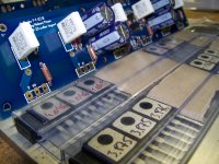
Amp will not be running this week. Measured up some mosfets.
Decided to compare the results of measured Vgs threshold using a Peak Atlas DCA with more conventional Vgs measurents at higher currents, e.g. around operating conditions.
I found there is an extremely good correlation between the two measurements ie I feel very confident selecting mosfets based on matching Vgs threshold using a simple component tester like the Peak Atlas ie if they are matched to within 0.02V at threshold they also match surprising well at other higher operating currents.
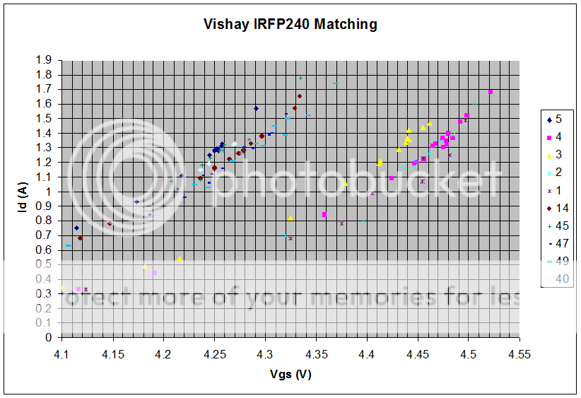
Last edited:
- Home
- Amplifiers
- Pass Labs
- F4 power amplifier