Hi Zen Mod,")
you suggested:
"omit output caps on , omit everything in front of two electrolyt caps on F4 input ( tossing out jfet buffer and everything related) , bypassing two elcos with 10-68nF polycarbonats ........ then tell me what's your impression"
I am going in balanced, but going out unbalanced to F4. Should I also omit the caps of the output shortened and then shorten the unused output?
I hesitate a little bit because the voltage on the outputs of pumpkin is coming down very slowly to zero volt. I lasts about ten to fifteen minutes. Is this behaviour o.k.?
Should I keep the output cap of the unused and shortened output?
I dont´t want to destroy pumpkin!!!!!!!!
Hi Zen Mod,
you suggested:
.........
I'll prepare little sketch later
no need to worry .....

Hi Zen Mod,
you suggested:
"omit output caps on , omit everything in front of two electrolyt caps on F4 input ( tossing out jfet buffer and everything related) , bypassing two elcos with 10-68nF polycarbonats ........ then tell me what's your impression"
I am going in balanced, but going out unbalanced to F4. Should I also omit the caps of the output shortened and then shorten the unused output?
I hesitate a little bit because the voltage on the outputs of pumpkin is coming down very slowly to zero volt. I lasts about ten to fifteen minutes. Is this behaviour o.k.?
Should I keep the output cap of the unused and shortened output?
I dont´t want to destroy pumpkin!!!!!!!!
naah ..... no need for sketch
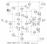
use F4 schematic from post #2994
connect
 as usual ( pos out to F4 , neg to gnd ) then bridge output cap on positive out with piece of wire .
nothing wrong will happen - ya see that 10K from output to gnd in Pumpie itself ?
Hi Zen Mod,
I modified, genergMod is happy!
What a sound, so natural. The the "k3 sound of F5" is very impressive, but you always want more and more details. F4 doesn´t reveal so much, but keeps more coherence and the details come as a surprise!
This keeps me calm and emotionally more satisfied.......
Pumpkin and of cause the wonderful DIY-amplifiers of Mr. Pass deserves the best attenuators in front of them you can get. I tried many possibilities, tvc (slagle) and a stepped attenuator (glasshouse) were the best in my chain.
Thank you again for helping so fast and competent!


Help with F4- no sound
Hi all,
Several months ago, I built a pair of F4 monoblocks using Peter Dianiel's boards. Worked good until yesterday, when I lost sound from left channel (right channel continued to work well). Substitution of different amp (nothing else changed) restored sound.
Voltage across all six 0.47R resistors (R16-R21) is 200mV at start-up. DC offset at binding posts is 30mV at start-up. Input RCA has correct continuity with signal and ground on PB. I cannot see any loose wires or smell burning. I do not know what else to check.
Any help tracking down the problem would be greatly appreciated.
Thanks
Gary
F4 as a headphone amplifier
Hello
I have started building my second pair of F4 on Villers PCB. This time I intend to try out how it will work as a headphone amplifier for my AKG K701.
I do need some adwises form someone with a better electronic understanding than myself about (still running in classe A):
Power voltage (lower than +/- 23 V if possible) and bias per device.
Preamp will be B1
Specifications AKG K 701
Type: Circumaural, open back headphones
Efficiency: 105 dB SPL /V
Maximum input power: 200 mW
Impedance: 62 Ohms
I have a lot of 220uF/16 V cond. Can I use them as C1/C2.
What about C3/C4?
Sincerely
Eivind Stillingen
You can run the amp at lower bias when your load is 62 ohm - but sounds like you already know that.
You can use the 16V caps on C1 and C2, but it might be a good idea to lower the voltage too. C3 and C4 will see a higher voltage, so you need to be careful with those. If you don't plan on using any gain, then you can lower the voltage quite a bit and still have plenty of swing without clipping.
You can use the 16V caps on C1 and C2, but it might be a good idea to lower the voltage too. C3 and C4 will see a higher voltage, so you need to be careful with those. If you don't plan on using any gain, then you can lower the voltage quite a bit and still have plenty of swing without clipping.
MPP from Joachim Gerhard
Hi Eivind,
Go to the thread of Joachim and go to the 4 last pages. You'll find all you need to make a good Phone amp for your AKG.
Just my 2 cents,
Audiofanatic
Hello
I have started building my second pair of F4 on Villers PCB. This time I intend to try out how it will work as a headphone amplifier for my AKG K701.
I do need some adwises form someone with a better electronic understanding than myself about (still running in classe A):
Power voltage (lower than +/- 23 V if possible) and bias per device.
Preamp will be B1
Specifications AKG K 701
Type: Circumaural, open back headphones
Efficiency: 105 dB SPL /V
Maximum input power: 200 mW
Impedance: 62 Ohms
I have a lot of 220uF/16 V cond. Can I use them as C1/C2.
What about C3/C4?
Sincerely
Eivind Stillingen
Hi Eivind,
Go to the thread of Joachim and go to the 4 last pages. You'll find all you need to make a good Phone amp for your AKG.
Just my 2 cents,
Audiofanatic
F4 as a headphone amplifier.
Audiofanatic
"Joachims thread". Can you please be more precise where to find this thread?
Thank you!
So to my question about a suitable power voltage and a corresponding bias for F4 driving my AKG K701 62 ohm imp.
How much can I reduce both and still be in classe A. The reason I ask has influence on how big heatsinks I must use (I already have two that I hope will fit)
Sincerely
Eivind Stillingen
post 1088
on this side i suppose ....
http://www.diyaudio.com/forums/analogue-source/154210-mpp-109.html
good luck!
on this side i suppose ....
http://www.diyaudio.com/forums/analogue-source/154210-mpp-109.html
good luck!
F4 as headphone amplifier
generg
You wrote:
".... do you know this version of F4?
Could be enough for your headphone".
Do you mean that this can do the job alone, without B1 as "pre"?
How do I fix a volumecontrol?
The PCB I use is from cviller. Here is the schema he use:
http://www.diyaudio.com/forums/blogs/cviller/198-my-f4-guide.html
As you can see, it is a little bit different from the version you show me. If I go for that version, as far as I can see, I have to keep Q3 and Q6 on cvillers PCB board and skip out the rest of IRF240/IRFP 9240? Will it be nessecary take away all 0,47/100 ohm resistors or can they stay (that will be the easiest way)??
D3/D4 out?
What about P2: 500 ohm versus 5 Kohm
R5: 1Kohm versus 3,32 Kohm
R22: 750 ohm versus 1 Kohm
Sincerely
Eivind Stillingen
- Home
- Amplifiers
- Pass Labs
- F4 power amplifier