OK those were hosted over at AC. I'll try attachments this time.
Moderator, feel free to delete post #2126 I tried to embed images in. Sorry for problem.
----------------------
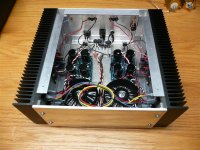
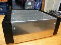
A couple images of my finished F4 "mule" amp with all Peter Daniels boards. This is my test bed before I start cleaning up wires, adding fancy parts, etc. Alas, metal work is not my forte, but it sounds great.
Tom
Moderator, feel free to delete post #2126 I tried to embed images in. Sorry for problem.
----------------------
A couple images of my finished F4 "mule" amp with all Peter Daniels boards. This is my test bed before I start cleaning up wires, adding fancy parts, etc. Alas, metal work is not my forte, but it sounds great.
Tom
Attachments
I have my F4 wired up with a single transformer driving a stereo amp. My tranny was initially bought for an AX amp that never materialized. It is a 750 VA 18v primary unit with a CLC power supply and about 65,000 uF of capacitance. The caps are 2200 uF Nichicon low ESR caps I bought on overstock for cheap and strung together on 11 ga romex.
Is there any real advantage to separate transformers for each channel? I have two of these monsters and they will end up driving 2 balanced channels in the end, but just wondered what if any advantage there would be to having two supplies instead of one.
Is there any real advantage to separate transformers for each channel? I have two of these monsters and they will end up driving 2 balanced channels in the end, but just wondered what if any advantage there would be to having two supplies instead of one.
Mine just has one AC inlet to dual transformers. I didn't think it was worth managing even more AC cords as I am in a bi-amped setup already.chrismercurio said:He has a dual mono stereo amplifier this way.
Do you have 2 AC inlets as well?
C
You get the best soundstage, using two trafo's (and supplies). True dualmono gives the best result, marginal maybe, but detectable. If you are building F4 bridged monoblock's, its perfectly allright with one trafo per channel. (Obviously!)
Another point is the appeal factor") but thats not important, compared to the previously mentioned reason.
but thats not important, compared to the previously mentioned reason.
One single AC inlet is quite adequate, though.
Another point is the appeal factor
but thats not important, compared to the previously mentioned reason.One single AC inlet is quite adequate, though.
Bolts and Stuff
TMS -
where did you get your bolts and washers for this?
Is there a kit for this sorta thing, or did you just go to the hardware store?
I would not mind seeing a close up of the PS, amp boards and rectifiers - looks like you got some quick disconnectors there, good idea.
Did you use 1/2 watt PRP resistors everywhere? Sorry if you posted parts used elsewhere.
Re: Bolts and Stuff
Uh, no kits, that's what DIY's about ;-)
I found a local Metal Supermarket franchise store here (GREAT service by the way). I had them cut a 5052 12x14 sheet of .125 aluminum for the pan (~$10), 12x6 .125 for the back (~$7), and 12x14 perf steel .080 on top (~$12). The front is 12x6 0.250 5052 (~$15). The angles are all 1 x 1 x.125 (~$1/ft). I have around $50 in all that, but then there's the 2 or 3 6-32 taps I broke hand threading all of them. That took by far more time than anything. I just don't have access to small job machine shop or friends with those tools. Oh, and a Unibit is worth every penny for the back panel.
I used all 1/2w PRP's except for Mills 5w for all 0.47R in the PS and source resistors. Coupling caps are Panasonic FC's, power supply 15,000uf 35v TSHA's, bridges are generic IR.
This is what I describe as a "mule" for me to test parts and get all the grounding right, etc before committing to more cost. I used the quick disconnects and left all the wires long so I could easily transplant all the parts later. The grounds are all connected using these cool little 6 position push in connectors from the electrical department at Menards. That way I could test how to ground the dual mono. Once it's right, I will use decent wire and solder all those connections permanently.
If you want to shoot me an email I can point you to more detailed pix.
Tom
mithomas said:TMS -
where did you get your bolts and washers for this?
Is there a kit for this sorta thing, or did you just go to the hardware store?
I would not mind seeing a close up of the PS, amp boards and rectifiers - looks like you got some quick disconnectors there, good idea.
Did you use 1/2 watt PRP resistors everywhere? Sorry if you posted parts used elsewhere.
Uh, no kits, that's what DIY's about ;-)
I found a local Metal Supermarket franchise store here (GREAT service by the way). I had them cut a 5052 12x14 sheet of .125 aluminum for the pan (~$10), 12x6 .125 for the back (~$7), and 12x14 perf steel .080 on top (~$12). The front is 12x6 0.250 5052 (~$15). The angles are all 1 x 1 x.125 (~$1/ft). I have around $50 in all that, but then there's the 2 or 3 6-32 taps I broke hand threading all of them. That took by far more time than anything. I just don't have access to small job machine shop or friends with those tools. Oh, and a Unibit is worth every penny for the back panel.
I used all 1/2w PRP's except for Mills 5w for all 0.47R in the PS and source resistors. Coupling caps are Panasonic FC's, power supply 15,000uf 35v TSHA's, bridges are generic IR.
This is what I describe as a "mule" for me to test parts and get all the grounding right, etc before committing to more cost. I used the quick disconnects and left all the wires long so I could easily transplant all the parts later. The grounds are all connected using these cool little 6 position push in connectors from the electrical department at Menards. That way I could test how to ground the dual mono. Once it's right, I will use decent wire and solder all those connections permanently.
If you want to shoot me an email I can point you to more detailed pix.
Tom
Email - thanks for the reply
TMS0425, I cannot mail you, says your blocked.
I think my profile will allow you to email me.
I have been waiting for a metals depot order once I get some 'real' heatsinks.
So you tapped the sides. I was hoping to drill and use some self tapping bolt.
I have the DCX as well. I am not quite sure if I understand the pre-2496 setup real well, other than its being used as another gain stage. Not a bad idea, if I can get away with a passive or my 10db gain Ultrapath.
Re: F3 BOM
why don't you ask Peter ?
bubba177 said:could someone please point me in the direction of a BOM for the F3- i have peter daniels boards-thanks for your help-bubba177
why don't you ask Peter ?

i have looked at all the pics on this thread and am puzzled on the best way to run the grounds in an F4
a) take ps,outputboard,and speaker ground seperate to a star ground?
b)ground spreaker to output board then to ps board then to chassis ground?
c) something else?
please give me your input
bubba177
a) take ps,outputboard,and speaker ground seperate to a star ground?
b)ground spreaker to output board then to ps board then to chassis ground?
c) something else?
please give me your input
bubba177
Please help with PSU questions
Hello everyone...greetings from Malaysia.
I am a non-electrical newbie here and have been reading the posts here and then some for the past few months now. I have a few questions and would appreciate if you all can help me out. I am building the F4.
I have a transformer with 2x 0-30V secondaries, rated at 530VA.
1. Can I run F4 rails at +/- 36~38V? What do I need to scale up (based on rev R0, I'm thinking R5, R22, and maybe the source resistors for better? stability?).
2. With rails at say 38V, I can only bias at 0.35A per mosfet and for a grand total of 4 mosfets (2N+2P). Is this bias too low? What is the lowest bias I can go and still sound good. The reason is I already have a smallish heat sink - about 0.25 C/W).
3. Which is preferred and why, 36V rail x 0.35A bias x 2 N+P sets or 20V rail x 0.45A bias x 3 N+P sets? Heat dissipation for both is about the same at 50W.
Thanks.
- Home
- Amplifiers
- Pass Labs
- F4 power amplifier