

With 14dB global feedback, the damping factor is about 270 and this agrees well with the simulation results.
BTW: I found an error in the simulation file in post #1554. RflbP2 should have been 28.7k and RlfbN2 should have been 31.3k.
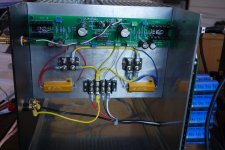
The bench tests use the parallel bias servo, not the series-parallel hybrid. I have been very careful in my measurements to prevent the errors due the the bias changing during the measurement, by applying a short duration input signal, usually than one second. For low power (<=5W) levels the bias change does not appear to be significant, allowing the input signal to be applied for a longer duration, providing a lower noise floor in the power spectrum.
What is the benefit of your opto bias vs a tl431 setup as in the schematic below?
Temp drift?
Attachments
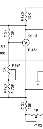
Yes temperature drift. With adequate degeneration the tl431 voltage generator works well, but with undegenerated FETs, in most cases. Some of the lateral FETs have a temperature coefficient that stabilizes them without the need for degeneration.What is the benefit of your opto bias vs a tl431 setup as in the schematic below?
Temp drift?
Yes temperature drift. With adequate degeneration the tl431 voltage generator works well, but with undegenerated FETs, in most cases. Some of the lateral FETs have a temperature coefficient that stabilizes them without the need for degeneration.
When i play around with your parallel bias as you have shown in THIS post. The Rcs resistor comes down to about 2kohm. For a bias of 1amp. RbsrN/P i use 10kohm. Current through the opto seems around 40mA then. This seems rather high.
Thoughts?
The RCS resistor should be greater than 27K and the cuureent thru the LEDs should not be greater than 1mA. The current through the RbsrN/P resistors should be around 1mA.When i play around with your parallel bias as you have shown in THIS post. The Rcs resistor comes down to about 2kohm. For a bias of 1amp. RbsrN/P i use 10kohm. Current through the opto seems around 40mA then. This seems rather high.
Thoughts?
The RCS resistor should be greater than 27K and the cuureent thru the LEDs should not be greater than 1mA. The current through the RbsrN/P resistors should be around 1mA.
Ill play some more... Maybe my spice model for the pc817 is no good.
I have spent many days analyzing the circuit equations for the source follower output stage using undegenerated square-law FETs. Below is a summary of my findings. In later posts I will show the equations for the harmonics applied to my ZD25 amplifier.
Attachments


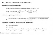

I have spent many days analyzing the circuit equations for the source follower output stage using undegenerated square-law FETs. Below is a summary of my findings. In later posts I will show the equations for the harmonics applied to my ZD25 amplifier.
I can see the usefullness of these. If you want to optimize a component or components for a particular degree of freedom, you could just calculate the component value instead of hunting for hours with LT SPICE.
LH Quam, you should write a book. Seriously. Or at least a chapter in Bob Cordel's next edition of his book.
I intend to so a similar analysis for common source push-pull undegenerated FETS. I have thought about handling source resistor degeneration, but the equations get considerably more complicated.
If the system of equations is too messy to simplify, turn the system of equations into a couple of dozen lines of C code. That approach may seem to be no more useful than SPICE, but having your own page of code lets you write loops to iterate and solve for things that you wish to have solved.
I did this for loudspeaker box alignments when designing some woofer drivers. Much more satisfying than making endless CAD scenarios one at a time. You can see all of the possible scenarios in one text file.
If practical, I much prefer seeing analytic solutions in order to better understand how then circuit parameters interact.
For very simple circuits LTSpice is quite fast, but sometimes it requires special programs to analyze the .log file data generated by from parameter stepping.
For very simple circuits LTSpice is quite fast, but sometimes it requires special programs to analyze the .log file data generated by from parameter stepping.
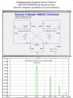
Undegenerated FET PushPull Output Stages with Ideal Front Ends
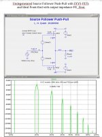
After considerable mathematical analysis of the source follower push-pull output stage using ideal square FETs, I decided to run some simulations with real world FETs and some circuit variants. The FET models used in these simulations include the unwanted parasitic parameters Rs, lambda, and all of the internal capacitances.
Here are some interesting results.
The 1st circuit is the SFPP using IXYS FETs and a simulation at 25W, 1kHz, 8R load with FE_Zout =100R. The harmonic spectrum shows a very nice uniform decline in the harmonic levels with frequency. But note that the even harmonics are are not canceled.
What would the harmonic spectrum be if the FETs were perfect FETS in the push-pull circuit? Since there are no perfectly matched FET NMOS
and PMOS FETs, I show a circlotron circuit using a pair of identical FETs
The 2nd circuit shows an NMOS source follower circlotron with an ideal front end. I have no idea how to build the front end. The harmonic spectrum show complete cancellation of the even harmonics, but similar levels for the odd harmonics.
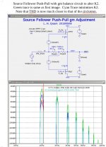
The 3rd circuit shown below shows a added potentiometer for adjusting the K2 level and phase of the output stage. In the example shown, a 200R pot is show with the Xgm adjustment value for minimum K2. I do not know if this is my invention or has been previously used.
After considerable mathematical analysis of the source follower push-pull output stage using ideal square FETs, I decided to run some simulations with real world FETs and some circuit variants. The FET models used in these simulations include the unwanted parasitic parameters Rs, lambda, and all of the internal capacitances.
Here are some interesting results.
The 1st circuit is the SFPP using IXYS FETs and a simulation at 25W, 1kHz, 8R load with FE_Zout =100R. The harmonic spectrum shows a very nice uniform decline in the harmonic levels with frequency. But note that the even harmonics are are not canceled.
What would the harmonic spectrum be if the FETs were perfect FETS in the push-pull circuit? Since there are no perfectly matched FET NMOS
and PMOS FETs, I show a circlotron circuit using a pair of identical FETs
The 2nd circuit shows an NMOS source follower circlotron with an ideal front end. I have no idea how to build the front end. The harmonic spectrum show complete cancellation of the even harmonics, but similar levels for the odd harmonics.
The 3rd circuit shown below shows a added potentiometer for adjusting the K2 level and phase of the output stage. In the example shown, a 200R pot is show with the Xgm adjustment value for minimum K2. I do not know if this is my invention or has been previously used.
Attachments
It is nice to see you pushing on with this even if I don't completely understand the purpose just now. Probably I am missing something, but aren't all three of the results above as expected?
I've not seen your particular arrangement for adjusting K2 level before but isn't it effectively just an attenuator for the input to the PMOS FET, thereby better matching the contribution of the NMOS FET?
I've not seen your particular arrangement for adjusting K2 level before but isn't it effectively just an attenuator for the input to the PMOS FET, thereby better matching the contribution of the NMOS FET?
- Home
- Amplifiers
- Pass Labs
- F4 Beast Builders