200 Amp, are you driving ribbons with a 5 volt supply?
should work quite well with a good unity gain stable op amp driving high bias ( 5 amp) output transistors in a non switching config. Vgs swing must exceed power rails by 6 ish volts for full current peaks.
supply droop will be more then a minor annoyance.
A Weller Trigger soldering gun fed with a 100w SS or tube amp will allow you to test the theory. Drive the ribbon off the soldering tip connections with AT LEAST 6 guage wire.
I started with + / - 6V on the hockey pucks. The I moved to +/- 12V. Now I am at +/- 24 v which is the same as the bias+input buffer supply just for ease of use during design and assembly. The final version will have lower hockey puck voltage.
Supply droop is one of the most challenging problems. Its easy to measure by pulsing the OPS into high current. My sig gen has one-shot pulse mode and the scope has a one-shot capture mode. The load can be a 0.01 ohms 3W resistor as long as the average energy over a second is nearly zero.
I am not sure what your soldering iron test is intended to show. Can you illuminate more?
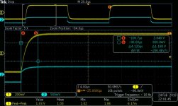
The input capacitance of the OPS is causing the 50 ohm sig gen to slew. Here is a measurement of the rise time portion of a 1kHz square wave. Blue is the sig gen output and yellow is the output of the pucks.
I am wondering if the K170/J74 input pair can drive these beastie pucks?
If not, is there a simple buffer circuit for the FQP3P20 and its complement to drive these pucks?
I am wondering if the K170/J74 input pair can drive these beastie pucks?
If not, is there a simple buffer circuit for the FQP3P20 and its complement to drive these pucks?
Take the Sony II input stage and it drives the pucks.
Thanks generg. The Sony II front end looks similar to the BA3 preamp circuit except the Sony II input stage is cascode. Is there any difference in drive capability between the two circuits?
The 140w Trigger soldering gun is essentially a 110v transformer to .5v at 300A as it constitutes a single turn on the secondary.
I was thinking this would be an easier way to test your project to ensure that the effort to build a super high current amp is worth the effort.
two 1000w computer power supplies should be able to deliver 200A peak on each rail.
however even at 5v that will be 1000 watts of heat to dissapate
I was thinking this would be an easier way to test your project to ensure that the effort to build a super high current amp is worth the effort.
two 1000w computer power supplies should be able to deliver 200A peak on each rail.
however even at 5v that will be 1000 watts of heat to dissapate
No I dont think there are big differences. Besides feedback and different load resistors.
What voltage do you use for the pucks?
24V for the bias circuit and the same 24V for the pucks. This is just for now. After it is all working, I will reduce voltage on the pucks for high current testing.
The 140w Trigger soldering gun is essentially a 110v transformer to .5v at 300A as it constitutes a single turn on the secondary.
I was thinking this would be an easier way to test your project to ensure that the effort to build a super high current amp is worth the effort.
two 1000w computer power supplies should be able to deliver 200A peak on each rail.
however even at 5v that will be 1000 watts of heat to dissapate
Ok. I think I get your suggestion.
The peak power is high but the average power will be low. So, I am not worried about frying ribbon tweeter diaphragms.
The soldering gun runs at 60 Hz and the inductance will likely be high and possibly problematic for making 10kHz pulses. No way to know until a trial run. I will keep this under advisement and revisit if needed. Thanks!
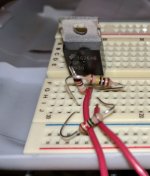
As Nelson suggested in the Citation thread, I should be building. So, I finished breadboarding an F4 and took measurements.
The breadbord is missing D1, D2 D3, D4 since I do not have these parts. They are in transit.
The breadboard is also missing R24, R25, C3, C4. I do not have any small 220uF caps but they are on order and in transit.
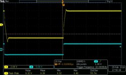
The breadboarded F4 driving the pucks does a good job with sine waves.
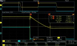
Attached is a capture of the breadboarded F4 passing a 10 kHz sine wave. The load is a 47 ohm power resistor. You can see the output slewing.
The second capture is a zoom-in of the falling edge. There is ringing at the onset of the falling edge. The slew rate is about 1.7 v/ uS.
The breadbord is missing D1, D2 D3, D4 since I do not have these parts. They are in transit.
The breadboard is also missing R24, R25, C3, C4. I do not have any small 220uF caps but they are on order and in transit.
The breadboarded F4 driving the pucks does a good job with sine waves.
Attached is a capture of the breadboarded F4 passing a 10 kHz sine wave. The load is a 47 ohm power resistor. You can see the output slewing.
The second capture is a zoom-in of the falling edge. There is ringing at the onset of the falling edge. The slew rate is about 1.7 v/ uS.
Attachments
Most of the Puck Amp Builders aim for a high voltage for the Pucks.
Form 40-70V. I suppose to minimize Crss.
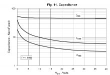
The N-channel puck I chose has a Vds max of 40v. The Ciss is fairly immune to voltage and is a steady 45 nF pe the datasheet.
I will fire up the LCR measurement gear and see what I can measure.
Another thing I can try is to hook up a Crown DC 300A to drive the pucks and see if that produces a better looking square wave.
As far as I know if you build a source follower the Crss is more decisive and and this one changes much with the voltage.
Attached are the curves for the n-channel puck capacitances. Crss is the lowest of the three and at 24v, it is close to its lowest value. It looks like I will have to deal with it as it is. It will get worse if I drop back to 12V. For this application, I do not see running the OPS higher than 15V.
Attachments
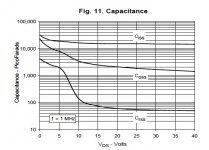
yeah, but you have 3nF Crss and look what the amp builders I mentioned seem to prefer...... :--))
Wow. The pucks you guys are using are worse for Crss.
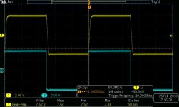
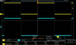
In the attached scope shot, the yellow signal is the scope probe comp signal driving a commercial amp. The commercial amp is driving the F4 beast OPS. The blue signal is the F4 beast OPS output to a 47 ohm resistor. The commercial amp has no problem driving the pucks and the pucks have no problem producing a nice square wave.
It is clear that the JFET 170/74 pair cannot drive these pucks with this topology.
Next stop is a two-stage IPS to drive the pucks.
It is clear that the JFET 170/74 pair cannot drive these pucks with this topology.
Next stop is a two-stage IPS to drive the pucks.
Attachments
Sloooooowwww progress is progress. The F4 solution does not work.
I went back to the drawing board, read more of the PassDiy site and Firstwatt site and some threads here.
The next iteration will be using parts already in my stash. I bought some LATFETs for a CFA amp that I breadboarded but never built a version to listen to.
These LATFETs will be combined with the input JFETs to make an almost F7 to be used as the driver for the hockey pucks.
An FQP3N30 will be the bias spreader. I slapped this together and tweaked it for about 7.2V which will bias the hockey pucks into conduction.
The new goal is to have a DC coupled F4 beast, possibly with no capacitors in the audio circuit.
Attachments
optocoupler bias circuits part 1
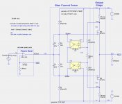
Here is the first installment on a series of posts about the behavior of some optocoupler circuits. My first post is about the behavior of the optocoupler pair with the transistor output connected in series.
The first image below is an example circuit with that topology.
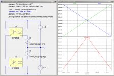
The second image shows the behavior of the series connected optocoupler transistors at very low frequencies. The output current is approximately the minimum of the LED currents.
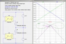
The third image shows the frequency response behavior at 10Hz, 100Hz, 1kHz, and 10kHz. As can be seen, the optocoupler time constants, mostly due to the output transistors, have a significant effect af the frequency increases.
In following posts I will show how this optocoupler tologoly affects the bias behavior of an amplifier such as the XA25.
Here is the first installment on a series of posts about the behavior of some optocoupler circuits. My first post is about the behavior of the optocoupler pair with the transistor output connected in series.
The first image below is an example circuit with that topology.
The second image shows the behavior of the series connected optocoupler transistors at very low frequencies. The output current is approximately the minimum of the LED currents.
The third image shows the frequency response behavior at 10Hz, 100Hz, 1kHz, and 10kHz. As can be seen, the optocoupler time constants, mostly due to the output transistors, have a significant effect af the frequency increases.
In following posts I will show how this optocoupler tologoly affects the bias behavior of an amplifier such as the XA25.
Attachments
- Home
- Amplifiers
- Pass Labs
- F4 Beast Builders