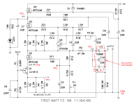
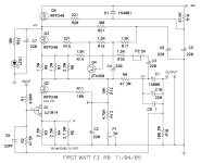
it is iterative process where 3 points are of importance:
to have 21V at TP1, while having 3V5 at TP4 and having 1V1 at TP3
in short, fiddling with P1, and changing value of R5, you need to get there
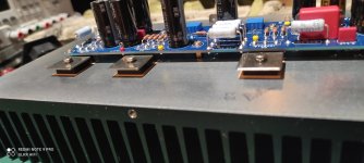
thermal paste is not needed with Keratherm 86/82 ..... and, in principle, it can just make things worse, simply bu introducing another factor doing the same thing as Keratherm film is doing
with Keratherm, there are "just" two things important to keep eye on - exact type (86/82) and to not over-torque
to have 21V at TP1, while having 3V5 at TP4 and having 1V1 at TP3
in short, fiddling with P1, and changing value of R5, you need to get there
thermal paste is not needed with Keratherm 86/82 ..... and, in principle, it can just make things worse, simply bu introducing another factor doing the same thing as Keratherm film is doing
with Keratherm, there are "just" two things important to keep eye on - exact type (86/82) and to not over-torque
Thanks for the info Zen, I maybe didn’t explain well enough, but I didn’t use thermal paste between the keratherm and the heatsink. It is just the keratherm 86/92. I used thermal paste between the aluminium L profile and the outer heatsinks. I tightened the m3 screws of the fets lightly but firmly with an Allen key, not full torque.
Btw temperature of heatsinks is around 42 degrees, 20-22 above ambient.
I will have to order some 3w resistors. Is there a good alternative for the Panasonics? Don’t seem to find much values on mouser or digi.
And going of the measurements I gave, would values between 2R5 and 3R5 be enough to get there? Or better order also higher values?
Thanks
you can look anywhere ( TME, Digi, Mou) - just search by through-hole, 3W, MetalFilm/Metaloxide
pretty much any Drek you find that way should work with no worries
now, which values ..... it seems that you need slightly increased value for R5, maybe trying standard value of 3R3 then - if change is too big, adding another resistor in parallel , to get it down from 3R3
example - 3R3 is too much, add 33R/1W across, resulting in 3R3//33R=3R
way of deciding/setting sometimes is to have a bunch of cheap 5W WW resistors, doing a test with those then when you know exactly what you need, buying final resistors in quality
Last edited:
") will order some resistors soon and then give it a go.
will order some resistors soon and then give it a go.Has anyone built the F3 and had low power output and low gain issues?
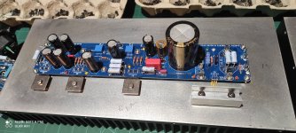
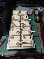
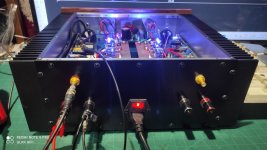
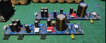
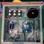
I've designed my own boards, sticking to the original schematic.
All my test points voltages are correct as per specs with no load.
I'm using real lu1014 from papa,
As soo as I add an 8 Ohm load and input 1.6vac 1k sine input, I get 1.9Vac out only just before negative sine clipping,
And my 2.5VDS across the lu1014 drops to 0.3V and the 21Vdc drops to 15Vdc.
Everything looks perfect, until I add a signal and those voltages sag, and the negative sine only soft clips to nothing.
Any insight or help is appreciated.
Attachments
So without any input signal you're getting the voltages as indicated? Is that with the input grounded?
What are you using as a signal source for the test signal?
Also, do both channels behave the same way? Anything different when you disconnect one channel from the PSU?
What are you using as a signal source for the test signal?
Also, do both channels behave the same way? Anything different when you disconnect one channel from the PSU?
Attachments
Without input signal I am getting all correct voltages.
With signal input and no load I am getting 3.8vac output just before negative sine clipping.
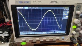
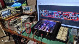
For my signal source I am using the Rigol DG4062 function generator.
My scope is the SIGLENT Sds 1102X.
My bench multimeter is the RS PRO RSDM-9061.
My hand multimeter is the Brymen BM869s.
Also the Brymen BM786.
My test load is a custom non inductive one.
Both channels behave the same way, and the regulation voltage on the board does not change during testing,
The main psu voltage does not sag.
I have a very good psu setup,
500va 35vac, so 250va per channel into 130000uF x2 with 0.25Ohm low pass in between.
I feel like I must have made a board error, I will go through everything again tomorrow and check everything.
I take it most people get the proper gain and power levels when they build this amp.
Thank you for your reply
With signal input and no load I am getting 3.8vac output just before negative sine clipping.
For my signal source I am using the Rigol DG4062 function generator.
My scope is the SIGLENT Sds 1102X.
My bench multimeter is the RS PRO RSDM-9061.
My hand multimeter is the Brymen BM869s.
Also the Brymen BM786.
My test load is a custom non inductive one.
Both channels behave the same way, and the regulation voltage on the board does not change during testing,
The main psu voltage does not sag.
I have a very good psu setup,
500va 35vac, so 250va per channel into 130000uF x2 with 0.25Ohm low pass in between.
I feel like I must have made a board error, I will go through everything again tomorrow and check everything.
I take it most people get the proper gain and power levels when they build this amp.
Thank you for your reply
Attachments
OK guys, a strange turn of events,
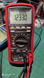
The output on both channels are now running 10.5vac in 1k,
To 12.3vac rms out into the 8 Ohm load.
Nothing in my test setup changed, everything exactly the same.
Only the amp isn't at full 50 degree temp yet.
Will continue to test and update my progress.
Is this way too low gain still?
Power output seems to be where its meant to be.
Gain isn't an issue for me, I've made my own cascode BA3 preamp that's capable of 30vrms output lol, so no worries about driving anything.
Attachments
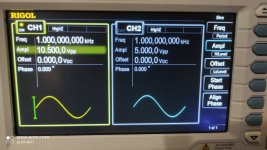
take both input and output in same manner - either Upp or Urms, then you'll know your gain
as I read it now, you have 10V5pp in, 12V3rms out
that being (10V55pp/2/1.41)rms to 12V3rms
ends 3V73rms to 12V3rms
gain ~3.3V/V = +10db
Pa declared +13db for original one, which is slightly more ....... ~4.5V/V
so, time for repeated measurements .......... of everything
as I read it now, you have 10V5pp in, 12V3rms out
that being (10V55pp/2/1.41)rms to 12V3rms
ends 3V73rms to 12V3rms
gain ~3.3V/V = +10db
Pa declared +13db for original one, which is slightly more ....... ~4.5V/V
so, time for repeated measurements .......... of everything

Thanks, I am very careful with my builds.
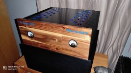
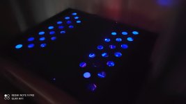
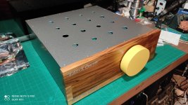
I also design all boards myself and hand make everything. Including my boxs/chassis.
Strange part is it was effecting both channels exactly the same,
I'm starting to think that the output caps needed to Form perhaps.
I also design all boards myself and hand make everything. Including my boxs/chassis.
Strange part is it was effecting both channels exactly the same,
I'm starting to think that the output caps needed to Form perhaps.
Attachments

First listening session tonight,
Sounds amazing,
It's been paired with my cascode BA3 preamp at the moment.
Impressed with the sound of this amp.
Sounds amazing,
It's been paired with my cascode BA3 preamp at the moment.
Impressed with the sound of this amp.
Attachments
Question for the group:
Given the ~ 100w/ch dissipation of the F3, and for those of you who are using the Modushop 4U/300, how hot are your heatsinks overall? How many degrees above ambient (and please state your ambient temp if known)?
I’m toying with the idea of using a 5U/300 instead but won’t if the 4U/300 isn’t scorching


My limit is about 50-55deg C in general. Otherwise, then BabySitter or just going for a 5U/300.
Best,
Anand.
Given the ~ 100w/ch dissipation of the F3, and for those of you who are using the Modushop 4U/300, how hot are your heatsinks overall? How many degrees above ambient (and please state your ambient temp if known)?
I’m toying with the idea of using a 5U/300 instead but won’t if the 4U/300 isn’t scorching
My limit is about 50-55deg C in general. Otherwise, then BabySitter or just going for a 5U/300.
Best,
Anand.
- Home
- Amplifiers
- Pass Labs
- F3 Builders Thread