I'm putting together my BOM and I'm most concerned at this moment with R3,4,5, the JFET source Rs's, R6,7,8, the CCS FET Source & Sense Rs, and R9 the output Sense R, and R10 the output bleed R. I think all of those would be bulk metal foils if $$$ made no difference, but it does. And I can't do that. Currently I'm thinking of Mills MRA-5s. 2.2Ohm(trim it later) for 3,4,and5, 1.2s for 6,7,8, .47 for the output I sense R, and 100ohm for the bleeder. That is a chunck of change right there but they fit O.K.. They have low temp coeficcients, and I can afford them. I'm also thinking a real Vishay Bulk Foil S102s for the 47k F.B. R, and an MK-132 7.5k for the Input R...
Any comments?? Contradictions or Suggestions??? I have more ideas but let's start with those...
Thx.
Any comments?? Contradictions or Suggestions??? I have more ideas but let's start with those...
Thx.
Hi FLG
That sounds pretty good to me.
If you think this will become your reference amp, then I think it is definitely worth spending the extra money on quality parts, espescially when you consider the amount of hours spent sourcing parts, building, and testing the amp, then the extra expense doesn't really sound too much in the end.
Thanks Babowana
The Panasonic 3W films are nice and at $0.51 they certainly don't mess up the budget but, I'm thinking the Tc of 300ppm vs the 50ppm of some other components may impart more of an unwanted contribution to the sound. With bulk metal foil type$ though, the Tc is maybe less than 10ppm. 
The components I mentioned are also streesed with power dissapation more than the others
All this is ignoring the resistance material's contribution otherwise of coarse And I have not actually heard the difference between all these types but, I've been happy with what I've heard using the MK-132s or MP930s. (proprietary "Micronox" film)
Granted this would be a very small non linear contribution compared to other areas of the system. However, it would be maganafied by a gain controlling component such as R3,4,5 or R1 and 2. I suppose the same improvement might not hurt with the treatment of R6,7,and 8? So, I don't suppose we would leave out R9 either. I think I'm willing to save a few bucks on R10.
The components I mentioned are also streesed with power dissapation more than the others
All this is ignoring the resistance material's contribution otherwise of coarse
And I have not actually heard the difference between all these types but, I've been happy with what I've heard using the MK-132s or MP930s. (proprietary "Micronox" film)Granted this would be a very small non linear contribution compared to other areas of the system. However, it would be maganafied by a gain controlling component such as R3,4,5 or R1 and 2.
I suppose the same improvement might not hurt with the treatment of R6,7,and 8? So, I don't suppose we would leave out R9 either. I think I'm willing to save a few bucks on R10. flg said:I'm thinking the Tc of 300ppm vs the 50ppm of some other components may impart more of an unwanted contribution to the sound.
I'll start worrying about that when semiconductors and tubes get better
than 50,000 ppm.
Thanks Nelson for putting some perspective on the matter.
I never realised how bad transistors were, I knew they were bad but I didn't realise they were that bad.
I am still in two minds about this though.
Even though the transistors make the biggest contribution to the sound quality of the amp, the number of transistors is small compared to passive parts.
Since their are a lot more passive components the affect of passive components on the sound will be cumulative, so what may seem a small effect on first thought may end up being significant when you add up the contribution of each passive part.
This is just me thinking. I have no real world listening experience on this, so you can take everything I said with a pinch of salt http://idioms.thefreedictionary.com/take+with+a+pinch+of+salt
Peter and others seem to think passive parts do matter though. I suppose it is finding the right balance.
Maybe we should start up two parts lists.
1) Peformance at all costs. (Total parts cost <$1000)
2) Best Bang For Buck (Total parts cost <$400)
This includes power supply components.
thanh1973 said:
Maybe we should start up two parts lists.
1) Peformance at all costs.
2) Best Bang For Buck
I almost always shoot for #2.
For F3-I am using RN55D resistors like Papa, and all Panasonic resistors except 2 ohmers, which were out of stock at Digikey.
I think detecting sound differences in resistors takes a fine ear.
My personal experience with caps is a different matter. I think crappy caps are easier to hear. Good one's less so. Certainly, I think most part swapping does make for a slightly different sound. The PCB's are not that expensive - I usually by more than needed and if inclined tweak one out, and compare to the defaults.
Usually I change only one part, as true troubleshooter, to see what changes I can hear.
I see your pointNelson Pass said:
I'll start worrying about that when semiconductors and tubes get better
than 50,000 ppm.
I suppose then, that one might not even worry about the transistors or tubes, until the speakers get better than 100000ppm thanh1973 said:Thanks Nelson for putting some perspective on the matter.
I never realised how bad transistors were, I knew they were bad but I didn't realise they were that bad.
We are talking about variations against temperature, as opposed to
distortion. Uncompensated, the bias of a bipolar or Mosfet in the
output stage can vary 100% between cold and hot.
On the other hand, I have seen tube circuits with 5% distortion before
feedback...
Sorry Nelson, for the misunderstanding.
It just that I had read else where that for some reason there seems to be a relationship between Tc of a resistor and sound quality.
So I thought you were also implying that transistors have the same sought of relationship and hence have the biggest negative affect on the sound.
It just that I had read else where that for some reason there seems to be a relationship between Tc of a resistor and sound quality.
So I thought you were also implying that transistors have the same sought of relationship and hence have the biggest negative affect on the sound.
thanh1973 said:Sorry Nelson, for the misunderstanding.
It just that I had read else where that for some reason there seems to be a relationship between Tc of a resistor and sound quality.
So I thought you were also implying that transistors have the same sought of relationship and hence have the biggest negative affect on the sound.
Well, there is a point to controlling the temperature of the active devices. I usually put some effort into keeping the temperature constant in my builds. In some cases that has gone as far as adding heat, to be able to control things.
Magura
thanh1973 said:Sorry Nelson, for the misunderstanding.
It just that I had read else where that for some reason there seems to be a relationship between Tc of a resistor and sound quality.
So I thought you were also implying that transistors have the same sought of relationship and hence have the biggest negative affect on the sound.
No need to be sorry, you gave me an opportunity to expand my point.
The active gain devices in any circuit are generally the worst performing
components, and if they weren't, we wouldn't need most of the other
parts to help clean them up.

Hi guys,
I'm collecting parts to build my F3, but after reading umpteen posts on the Power supply i'm more confused then ever.
Is 300VA 18+18 V toroid or Rcore ok for powering both channels ?
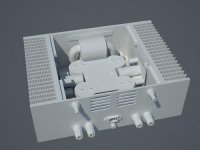
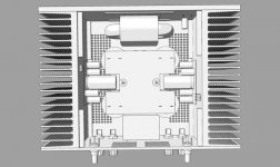
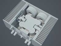
Here is a rendering of my proposed layout, to scale!
Heatsinks are from Mali Elektronika, HR-245 rated at 0,25ºC/W
( 300x150x83 ).
The big PS Caps are 15000uF/63v superthrus.
The output cap is a 15000uF/63V 4pole Jensen.
The diode bridges are MURs bolted to the bottom of case between the PS Caps.
Apart from clearing up my doubts on the transformer any other coments are more than welcome.
I'm collecting parts to build my F3, but after reading umpteen posts on the Power supply i'm more confused then ever.
Is 300VA 18+18 V toroid or Rcore ok for powering both channels ?
Here is a rendering of my proposed layout, to scale!
Heatsinks are from Mali Elektronika, HR-245 rated at 0,25ºC/W
( 300x150x83 ).
The big PS Caps are 15000uF/63v superthrus.
The output cap is a 15000uF/63V 4pole Jensen.
The diode bridges are MURs bolted to the bottom of case between the PS Caps.
Apart from clearing up my doubts on the transformer any other coments are more than welcome.
Attachments
CeeVee said:Hi guys,
I'm collecting parts to build my F3, but after reading umpteen posts on the Power supply i'm more confused then ever.
Is 300VA 18+18 V toroid or Rcore ok for powering both channels ?
Here is a rendering of my proposed layout, to scale!
Heatsinks are from Mali Elektronika, HR-245 rated at 0,25ºC/W
( 300x150x83 ).
The big PS Caps are 15000uF/63v superthrus.
The output cap is a 15000uF/63V 4pole Jensen.
The diode bridges are MURs bolted to the bottom of case between the PS Caps.
Apart from clearing up my doubts on the transformer any other coments are more than welcome.
power consumption is 200W for stereo ;
for that - you need at least 400VA xformer .... ( one xformer for both channels)
heatsinks - 0,25C/W - seems enough
Nelson Pass said:
It would not be the first time, but I have a large quantity of 25V
caps, so I ran them in series from what would have normally been
a split supply. I made up for it with a big fat capacitor multiplier
on the supply.
I'm quite confused about the PS caps. In the F3 service manual there are 8 x 15000uF caps (each group of 4 in series / parallel) and this PSU powers both channels.
Q1: Would this be the same as having two 30000uF in each side of the resistors?
I will be taking Peter's board and split it in half to build two monoblocks. So each PSU will have to provide 46V but only half the current.
Q2: Will it be fine if I use two 15000uF x 50V or 63V to be on the safe side?
Q3: Should I change the value of R9 since it will have 46V across its pins?
Q4: Should I change the value of R1-R4 or should it stay at ~.12R?
I think I read somewhere that Peter used one 15000uF and one 10000uF with two .22 resistors in parallel but I can't remember if it was for the F3. Maybe for an F4 or F5....
For this configuration I'll need a transformer with a secondary of 36VAC and 200VA? Is this correct? I think I read somewhere that for a stereo version a 400VA transformer was needed.
Thank you,
Luis
EDIT: I knew I should have read the thread right to the very end....
CeeVee said:Thanks ZM,
..you again to the rescue
Here is a pic of 2x 225VA i found at Selectronic.....they fit nicely.
Ps: i haven´t forgoten the other thingie we are doing together...
fugly! , as usual from you , CeeVee .....
as I remember - you owe me some pics , in another thread .....

- Home
- Amplifiers
- Pass Labs
- F3 Builders Thread