Hi Paul,
You are right I screwed my drawing up U8 on the dwg is really U10, and U10 on the dwg is really U8.
Ray,
The ocillator is something that I'll check, I bought both the big 4 pin one and the smaller SMD crystec. I installed the SMD but had difficulty, I might have screwed it up. I don't have a scope but I'll go over everything with a powerful magnifying glass and check for shorts, and try reflowing the clock. If I don't find any thing and it still won't work, I'll try swapping the clock out for the big one.
Thanks for all of your help and patience,
PJN
Hi everyone,
I finally got some free time to try troubleshooting mu dac board some more. Unfortunately still no success but here is a run down on my findings so far.
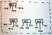
- All the voltage regulators U8,9,10, and 11 are putting out the correct voltage, except that U10 and 11 are putting out +10.6v and -10.6v instead of 12v. but thats just a resistor change to correct.
- PCM 1794 : getting 3.3v on legs 2 & 9 as per diagram, getting 5v on 15,21,22,23 & 28 as per diagram.
- AD1899 : geting 3.3v on proper legs as per diagram.
- CS 8416 : getting 3.3v to legs as per diagram.
- U4 & 5 : getting +10.6v on leg 7 and `10.6 on leg 4 as per diagram.
- I carefully checked the board for shorts under magnification and didn't find any.
- After the above checks I removed the SMC clock and replaced it with the 4 pin canned clock.
Still won't sing. I don't have any equipment other than a DMM. Any suggestions on what I could/should check next would be greatly appreciated.
Thanks,
PJN
I finally got some free time to try troubleshooting mu dac board some more. Unfortunately still no success but here is a run down on my findings so far.
- All the voltage regulators U8,9,10, and 11 are putting out the correct voltage, except that U10 and 11 are putting out +10.6v and -10.6v instead of 12v. but thats just a resistor change to correct.
- PCM 1794 : getting 3.3v on legs 2 & 9 as per diagram, getting 5v on 15,21,22,23 & 28 as per diagram.
- AD1899 : geting 3.3v on proper legs as per diagram.
- CS 8416 : getting 3.3v to legs as per diagram.
- U4 & 5 : getting +10.6v on leg 7 and `10.6 on leg 4 as per diagram.
- I carefully checked the board for shorts under magnification and didn't find any.
- After the above checks I removed the SMC clock and replaced it with the 4 pin canned clock.
Still won't sing. I don't have any equipment other than a DMM. Any suggestions on what I could/should check next would be greatly appreciated.
Thanks,
PJN
That's a good suggestion. The RESET output should be high (3.3V) under normal operation. It goes low (0V) for about 200 ms when power is first applied.A small suggestion: check if the RESET pins become high, +3.3V. If somehow things around U6 don't work correctly, the DAC remains in RESET state and there's no output either.
Ray

Hi guys,
I tooks some readings tonight with a digital source hooked up and running to the EZDAC. the PIC below shows what I got. The reset voltage was on spec. Do you think that its something upstream that's at fault ?
Thanks
PJN
Most voltages look o.k., only Vcom at pin 22 is not correct. This should be 2.25V, just like the other channel. I suspect you skipped a pin writing down the voltages. I don't know what REF at pin 20 should be. If you check and still find it's 2.25V, I suspect a short to Vcc could be the problem.
Ray
Hi Ray,
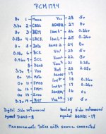
You were right, I rechecked pin 22 on the dac chip and got 2.25v. Those legs are really close together and I must have hit the Vcc. I took a set of readings on both the AD1896 and the CS8416 and have attached them below.
PJN
You were right, I rechecked pin 22 on the dac chip and got 2.25v. Those legs are really close together and I must have hit the Vcc. I took a set of readings on both the AD1896 and the CS8416 and have attached them below.
PJN
Attachments
Hi Ray,
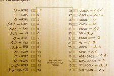
I double checked things tonite, on the CS8416 pin 12 was 3.3v, and on the ASRC pin 9 was 0v and pin 10 was 3.3. Those damn pins are so tiny and numerous that I find it easy to get lost.
I checked the clock pin 4 (Vdd) 0.77v and pin 3 (out) was 0.92v
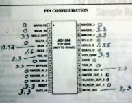
I checked U4 and U5 also, the results are in the pic. I noticed that even though I had inputs and voltages on pin 6 (Vr/Vl) I had no reading on either. I used the LME49710MA which was the alt on the BOM. I checked the legs carefully for shorts and bad solder joints but all looked good. Do you think I got a couple of bad chips ?
PJN
I double checked things tonite, on the CS8416 pin 12 was 3.3v, and on the ASRC pin 9 was 0v and pin 10 was 3.3. Those damn pins are so tiny and numerous that I find it easy to get lost.
I checked the clock pin 4 (Vdd) 0.77v and pin 3 (out) was 0.92v
I checked U4 and U5 also, the results are in the pic. I noticed that even though I had inputs and voltages on pin 6 (Vr/Vl) I had no reading on either. I used the LME49710MA which was the alt on the BOM. I checked the legs carefully for shorts and bad solder joints but all looked good. Do you think I got a couple of bad chips ?
PJN
Attachments
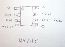
The readings on U4 and U5 are o.k. The opamp only amplifies the difference between it's inputs, so it's normal that you don't have any output on pin 6, since both 2 and 3 read the same.
But the clock voltages are not o.k. Pin 4 Vdd should read 3.3V and this may be the error that is keeping your ezDAC from singing! Without supply voltage, the oscillator won't do anything and there's no clock for the DAC. There's an SMD ferrite bead on the back of the board (F2) that transports Vdd to the oscillator, maybe it has a bad connection?
Regards,
Ray
- Status
- This old topic is closed. If you want to reopen this topic, contact a moderator using the "Report Post" button.
- Home
- Source & Line
- Digital Line Level
- ezDAC v.1.5 Builders Thread