t. said:Look at the left here just click on PFM fleahttp://www.acoustica.org.uk/ I had to modify the one for the XO to output 3,3v instead of 5v
I'm about to fit another to power the 5v section of the dac if I can squeeze it in
Thanks, just gave it a quick glance. It seems the current should be less than 100 mA or so, is that right? I wasn't sure exactly how much current is drawn by the various sections, but maybe that is o.k. in each case.
Hi,
one question about the EZDAC power supply: instead of using one PSU, is it possible to use one pre-regulated power supply for the the analog (AD8610) components and another pre-regulated power supply for the digital ones, continuing using the on board LM317-337 chips? All this to keep the digital and analogue circuits well separeted.
one question about the EZDAC power supply: instead of using one PSU, is it possible to use one pre-regulated power supply for the the analog (AD8610) components and another pre-regulated power supply for the digital ones, continuing using the on board LM317-337 chips? All this to keep the digital and analogue circuits well separeted.
Heres the other Flea now running the 5v, only one left is the 3.3v, I need something thats more current
An externally hosted image should be here but it was not working when we last tested it.
Another piccy using the Burson buffer with the Ezdac, I'm currently using the Aksa N+ and UCD180 amps, so far I'm very pleased with the sound
Cheers,
Leo
An externally hosted image should be here but it was not working when we last tested it.
Cheers,
Leo
It's been a while, so I thought I'd post an update. Hao-Wu, a DIYer from Taiwan, built my ezdac recently (like a couple of days ago). He made some measurements. Here's a link:
http://www2.kumc.edu/students/ezamir/DIY/builders/haowu/1794.htm
http://www2.kumc.edu/students/ezamir/DIY/builders/haowu/1794.htm
EzDAC in progress...
Hi guys,
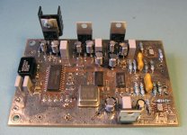
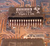
Here are a couple of pics of my EzDAC, still 'under construction'. The PCB is finished and tested, and my first impression is that it sounds very good. I used the 'fancy' chipset: AD1896A and PCM1794A with AD8610 opamps. I'm using three separate regulated PSUs for +/-12V and 3.3/5V; I cut the track between the 12V and 3.3/5V. The clock is going to be generated by a PFM Flea eventually and i'm planning to use a few Black Gates instead of the ZA's that are on the board now.
Regards,
Ray
Hi guys,
Here are a couple of pics of my EzDAC, still 'under construction'. The PCB is finished and tested, and my first impression is that it sounds very good. I used the 'fancy' chipset: AD1896A and PCM1794A with AD8610 opamps. I'm using three separate regulated PSUs for +/-12V and 3.3/5V; I cut the track between the 12V and 3.3/5V. The clock is going to be generated by a PFM Flea eventually and i'm planning to use a few Black Gates instead of the ZA's that are on the board now.
Regards,
Ray
Attachments
Re: EzDAC in progress...
Looking great, Ray.
In the pic the LM317 are mounted, so you are using 3 PSU (+/-12V and 3.3/5V), that feeds the on board LM317/337, right?
What about grounds? Please put some pic of the connections, when finished. I am willing to go the same way, with different PSU for each voltage, but bypassing on board LM3xx.
6h5c said:I'm using three separate regulated PSUs for +/-12V and 3.3/5V; I cut the track between the 12V and 3.3/5V.
Looking great, Ray.
In the pic the LM317 are mounted, so you are using 3 PSU (+/-12V and 3.3/5V), that feeds the on board LM317/337, right?
What about grounds? Please put some pic of the connections, when finished. I am willing to go the same way, with different PSU for each voltage, but bypassing on board LM3xx.
Hey, nice surprise to see another built! I'm sorry I didn't see the thread earlier. Ray, you should definitely put some pics over in the gallery section of my forum.
Also, I should let you guys know I only have a couple of boards left, so I'm thinking about what do for the next batch. From what I see, my design really should focus more on being a true modder's board. So, rather than focusing on improving the onboard regulation or output, I want to make it easier for people to mod those things. With that in mind, I think the only modifications to the design I will do is add jumpers, so you don't have to cut tracks, and add larger vias for directly connecting external regulated psu's. I will also make the pads for the I/V resistors larger, so you could easily tap them, if you want to do your own I/V (balanced). The core of the design (SPDIF->ASRC->PCM179X) will not change, as I think it should be viewed as a basic building block. And since you guys have already proven everything else can be modded, I think the board is already quite a success from that standpoint. There should be some DIY left in DIY, right?
Finally, if I knew there was enough demand, I would think about increasing the size of the board (which would create more space for terminal blocks), and adding silkscreen/soldermask. However, I would need to order at least 50 boards, to make that possible, without substantially increasing the price of each board.
Re: Re: EzDAC in progress...
Thanks guys. The outputstage was something that came to my mind too, when I saw the EzDAC project. I had a quick listen to it for the first time this week and used my modded SA8400 as a source (which has the output stage on-board). I had those analog outputs plugged in too, so I did a nice A-B comparison with my amp's selector switch. The EzDAC was temporarily soldered together with lots of loose wires and PSU PCBs. But it already sounds very good, and is definately of the same level of quality as the 8400 (it uses the CS4397 'Super DAC'). I'm curious what the end result will be, and how it will compare to SACD playback through the 8400's outputstage.
I wonder if a discrete stage with the EzDAC will contribute a lot. There's clearly some HF residue present on the scope, but it's way outside the audioband and doesn't seem to affect performance. So more filtering may not improve things much. It has a nice differential input though, maybe if you use it without the passive filter, or use a simplified 2nd order version of it. The signal should come out cleaner and the circuit is very simple, so that may be an advantage to the opamps.
Ray
t. said:Looking great ray
Thanks guys. The outputstage was something that came to my mind too, when I saw the EzDAC project
. I had a quick listen to it for the first time this week and used my modded SA8400 as a source (which has the output stage on-board). I had those analog outputs plugged in too, so I did a nice A-B comparison with my amp's selector switch. The EzDAC was temporarily soldered together with lots of loose wires and PSU PCBs. But it already sounds very good, and is definately of the same level of quality as the 8400 (it uses the CS4397 'Super DAC'). I'm curious what the end result will be, and how it will compare to SACD playback through the 8400's outputstage.I wonder if a discrete stage with the EzDAC will contribute a lot. There's clearly some HF residue present on the scope, but it's way outside the audioband and doesn't seem to affect performance. So more filtering may not improve things much. It has a nice differential input though, maybe if you use it without the passive filter, or use a simplified 2nd order version of it. The signal should come out cleaner and the circuit is very simple, so that may be an advantage to the opamps.
Ray
Originally posted by claudio
Looking great, Ray.
In the pic the LM317 are mounted, so you are using 3 PSU (+/-12V and 3.3/5V), that feeds the on board LM317/337, right?
What about grounds? Please put some pic of the connections, when finished. I am willing to go the same way, with different PSU for each voltage, but bypassing on board LM3xx.
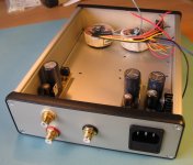
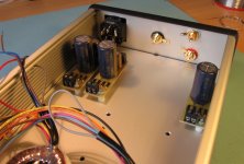
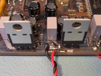
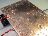
Yep, the three PSUs put out 9V and 2x 15V and feed the on-board regs. I used a simple 78xx circuit and two 7815's for the +/-12V section. I just wired one 15V output to GND to generate -15V. I used the local ground-plane to connect the PSU to ground, so it's closer to the on-board input capacitors. Here's a few pics.
Regards,
Ray
Attachments
Excellent news Ray
As you can see my Ezdac further up http://www.diyaudio.com/forums/showthread.php?postid=1180743#post1180743 I've added a few bits and pieces to mine, PFM flea for the 5v, Burson disrete regs for the +/-12v, PFM Flea for the XO, THS4031 op-amps, linked out the input Spdif 10nf cap on the positive in (my transport and modded SB3 already have coupling and pulse transormer)
Funny thing is I compared a few different type of caps including ZA's, few BG NX Hi-Q's, tants for the decoupling, for some reason I liked tants the best, if you can try comparing the 2 x 47uf types for the VCOM pins, I compared a few here, in my system these two caps had quite an effect on the sound, I now have temporary little sockets fitted on the VCOM pins to allow quick comparing
So far the sound is extremely good since doing the few mods, other thing I need is a discrete reg for the 3.3v, I wanted to use a modded flea but I think the current will be too high.
- Status
- This old topic is closed. If you want to reopen this topic, contact a moderator using the "Report Post" button.
- Home
- Source & Line
- Digital Source
- EZDAC is singing now!!!