If you want a secondary fuse then one in the CT is fine.
Heater supplies should not float, so the EZ81 heater secondary needs to be connected to something. Connecting it to ground puts a high voltage across the heater-cathode insulation - which is designed to cope with this, but may fail. Connecting it to the cathode puts a high voltage across the heater secondary insulation - which may or may not be designed to cope with this, possibly depending on the age of the transformer and exactly what the datasheet says. Using a highish value resistor as Osvaldo suggest would be a useful precaution.
Heater supplies should not float, so the EZ81 heater secondary needs to be connected to something. Connecting it to ground puts a high voltage across the heater-cathode insulation - which is designed to cope with this, but may fail. Connecting it to the cathode puts a high voltage across the heater secondary insulation - which may or may not be designed to cope with this, possibly depending on the age of the transformer and exactly what the datasheet says. Using a highish value resistor as Osvaldo suggest would be a useful precaution.
Not necessary, but in my own experience, recommended.hi
if i have a separate 6.3v winding for ez81 is it allso necessary to have the cathode and heater at the same potential?
I use a 47 or 100KΩ and a 1µF 400V from pin 5 to gnd. Also, nor the C nor the R are mandatory, but I use them, as in the DOS schematic.
100k, 1/2W?
This resistor does't conduct any current, so a 1/8W is sufficient, but for commodity I use ½W.
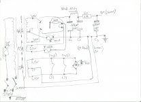
This is my circuit.
Attachments
Last edited:
Member
Joined 2009
Paid Member
I've never seen anybody worry about fusing the heater supply. A fuse on the primary side of the transformer should cover you unless you are worried about damaging an irreplaceable vintage power transformer I wouldn't bother.
For safety reasons I'd add bleeder resistors across the HT capacitors.
For safety reasons I'd add bleeder resistors across the HT capacitors.
hi
its not a irreplaceable vintage transformer, but its not fun replacing one as well")
is it ok to put one resistor to bleed all 3 caps? to my calculation a 155K resistor will drop to 30V in a minute +
hope i am right
i saw this when i read about heaters...-I've never seen anybody worry about fusing the heater supply. A fuse on the primary side of the transformer should cover you unless you are worried about damaging an irreplaceable vintage power transformer I wouldn't bother.
its not a irreplaceable vintage transformer, but its not fun replacing one as well
Transformer Centre Tap
The traditional way to reduce hum is to use a transformer with a centre tap, and connect it to ground. A refinement is to ground the centre tap through a small flame-proof resistor (anything up to 100 ohms). This will act as a fuse if there is a short between the anode and heater pins of the power valves, thereby reducing collateral damage.
For safety reasons I'd add bleeder resistors across the HT capacitors
is it ok to put one resistor to bleed all 3 caps? to my calculation a 155K resistor will drop to 30V in a minute +
hope i am right
No need to fuse heater supplies. The CT on a heater supply does a completely different job from the CT on a high voltage secondary, so fusing the heater CT achieves worse than nothing: it simply inserts a point of failure while protecting nothing. Think about where the currents flow.
hi
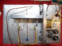
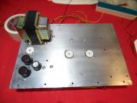
see below my ps as it is now
i started the preamp yesterday for the first time and took some measurements
i am geting 308V not 260V
so the plate V for the 12b4 is 116V not 90
i want to add a bleeder resistor, although the caps are bleeding when i close the amp (?)
if i add a bleeder resistor
1- will it drop the b+ ? ( before i change the 1K resistor )
2- were to place it for better regulation? C1 C2 C3 all of them?
3- how can i calculate the values of the resistor for better v regulation, W and R ?
so many questions ....
thank you all
Attachments
Running a circuit designed for 260V from 308V will do no harm.
A bleeder resistor is for safety, not voltage regulation. If you wanted better regulation with an unregulated PSU you should have used silicon diodes with a smaller secondary voltage. Valve rectifiers give poorer regulation.
A bleeder resistor is for safety, not voltage regulation. If you wanted better regulation with an unregulated PSU you should have used silicon diodes with a smaller secondary voltage. Valve rectifiers give poorer regulation.
tnx DF96
i just read somewere that placing aBR on a the choke cap can help, but didnt quite understend
the caps are bleeding when i close the amp so i dont worry about safety but i still check them with a meter and a screwdriver before handling the amp
i will change the 1K R to try and lower the B+ just because i have one ready...
I suggest two variants to the schematic:
1) remove the bridge diode and the led,
2) place a neon lamp in the +B to gnd, via a 200KΩ resistor.
This way, the lamp will indicate when +B is present, and also save the cost and space of the diodes. Also, neon lamps shut down at about 60V, indicating that +B is sufficient low to play in the equipment soon.
tnx Osvaldo
its a neat idea
i will look for this lamps localy or order some on line
the bridge diode was salvaged from a small charger and was all ready installed
i can have both, one for B+ and one for heaters
Surely, but it is useless to have two pilots in the same set, or not?
I use them (neon lamps) as zeners for voltage references in electronic tube regulators.
tnx i didnt i have 2 in a divider mode running low on 1.8vDon't forget the series resistor for the LED.
i found 2 neon lamps today i dont know what current, i guess 0.5 -3 mA...Surely, but it is useless to have two pilots in the same set, or not?
i'll try to place one in the +B to gnd, via a 220KΩ resistor like you suggested
hi again
as I wrought before I started the preamp and the B+ was a bit high 308V
so I replaced the 1K resistor with a 1.2K and then problems started…
sparks & smoke from the positive terminal on C3 100Uf/450V (not 500V like in the schema)
I replaced it back to 1K but still S&S from C3
Replaced the cap with a 47Uf/400V so I got S&S from positive terminal on C2
I thought maybe the current is to high so I tried putting limiting resistor between the cathode and C1 then the fuse on the CT of the HT blew
When disconnecting the smoothing circuit and measuring from the rectifier I get 292VDC and the from TR 635VAC
The chock is 10H/80ma with 200R DC
To my understanding probably too much current?
May be need smaller caps < 47uf ?
If smoke&sparks came from a cap can I use it for further testing's or its dead?
your help please
Attachments

- Status
- This old topic is closed. If you want to reopen this topic, contact a moderator using the "Report Post" button.
- Home
- Amplifiers
- Power Supplies
- EZ81 power supply