I should have mentioned it earlier, but it would be preferable to have Q7 & Q8 in the thermal vicinity of the drivers, or OP, or both: a current dumping amplifier doesn't need a true thermal compensation like traditional AB amps, but if the temperatures drift really very far apart, it could begin to cause problems.
No need for a tight thermal coupling, but some proximity would be beneficial.
I was planning on mounting transistors in 2 ways (didn't decide yet):
a) The drivers under the board, horizontally bolted to Alu plate - the same plate where output devices will be located; so no dedicated heatsink for drivers.
Output devices will be TO-3, connected to the board by wires, up to 5cm from the north edge of the PCB.
b) The drivers 'standing up', like in my Circlophone build, with dedicated heatsink. In this case OP devices can be on wires, or soldered directly to the board (TO-264)
I see one easy solution (beside redesigning the board):
Q7/Q8 can be soldered UNDER the board, in thermal contact with the the Alu plate - this will provide enough feedback, either from drivers + OP, or just from OP.
I think most of builders mounts boards on top of the heatsink, with OP transistors soldered to the PCB, and bolted to the heatsink underneath,
so this may work well.
Now - can they be replaced by some TO-126 devices?
Screwing TO-126 under the board to the Alu plate is much easier then using small transistor with glue...
Or perhaps just drill 2 holes under the board, where small transistors are mounted, and fill it up with thermal silicone, and they will hopefully fit right in.
Yeah, that's easy part, we even have some spare area still available on the board..Something else I forgot to mention: in its present form, the amplifier is completely DC-coupled. Some see it as an advantage, but in general people prefer AC coupling, because it keeps the output offset well under 10mV.
To make it AC-coupled, all that is needed is a 47µF or 100µF cap in series with R18; polarity is indifferent a it will never see more than a few mV, and the voltage can be as low as 2.5V.
Should be easy to implement if required
This amp should be tested first on the veroboard with wires, but it's gonna be a big mess, so I decided to go with pcb..
Yes, that sounds more than sufficient: the transistors just need to feel the heath, they do not even need an actual contact: proximity would be enoughI see one easy solution (beside redesigning the board):
Q7/Q8 can be soldered UNDER the board, in thermal contact with the the Alu plate - this will provide enough feedback, either from drivers + OP, or just from OP.
I think most of builders mounts boards on top of the heatsink, with OP transistors soldered to the PCB, and bolted to the heatsink underneath,
so this may work well.
Yes, certainly: in fact practically any TO126 will do, since their role is mostly voltage shifting.Now - can they be replaced by some TO-126 devices?
Any 500mA/30V (or even less if you find one) device would do.
As I said, if they are just facing the alu plate, even at some distance it is OK, but feel free to do better.....Screwing TO-126 under the board to the Alu plate is much easier then using small transistor with glue...
Or perhaps just drill 2 holes under the board, where small transistors are mounted, and fill it up with thermal silicone, and they will hopefully fit right in.
As usual, LV posts interesting stuff. But I found stability problems when simulating 20KHz. This circuit seems to be very fussy about transistor models, behaves differently with different output transistors, for example. And it can latch up if you if the feedback and bootstrap levels are too close, and you drive it to clipping.
I have done boot strapped IPS myself and found that you need to filter the high frequencies because the PSRR at high frequencies may be poor.
The global feedback worries me, asking for trouble.
The positive feedback is a brilliant idea but I think you need more to guarantee the input common mode range is never exceeded, causing latch-up.
I would post my simulations but none are perfectly solid/ better solutions, maybe later.
We will only have definitive answers when the thing is built.
Sims are great, but they have their limits.
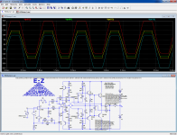
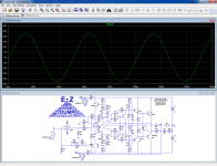
Regarding the CM range, it seems to remain well within the bounds of the bootstrapped supplies, even under heavy clipping.
Red trace is Vcc/U1, cyan Vee/U1, yellow and green in+ & in-:
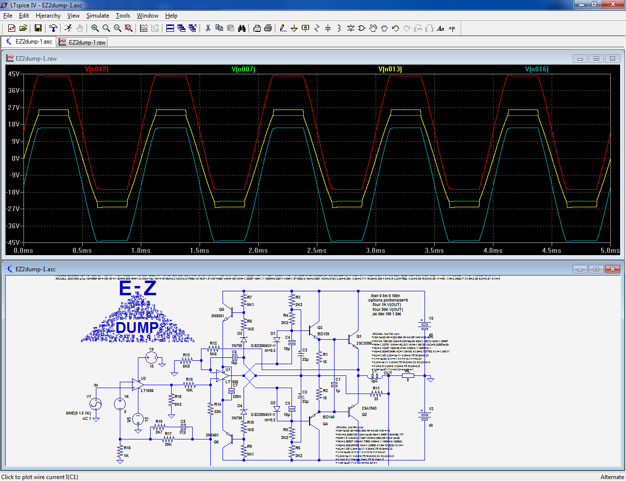
With a CD amp, some results can look disconcerting, because the modes of operation with just the class A and with class B are very different
Sims are great, but they have their limits.
Regarding the CM range, it seems to remain well within the bounds of the bootstrapped supplies, even under heavy clipping.
Red trace is Vcc/U1, cyan Vee/U1, yellow and green in+ & in-:
With a CD amp, some results can look disconcerting, because the modes of operation with just the class A and with class B are very different
Attachments
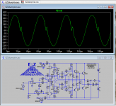
Fair enough. This image shows an example of the instability I see At 20KHz. It is very touchy and different xx3055 or xx2955 models dramatically change the result. BTW, 90VDC is too much for xx3055/2955 so you should use 5200s or similar.
So here are some things that stabilize this circuit.
1. Reduce the op-amp gain by hanging a resistor across in+ and in-.
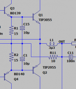
2. Reinforce the driver coupling to cover the class-C gap.
3. Lift the collectors of Q7,8, relegating them to VBE multipliers with no gain. I'm not sure exactly why, but this helps stability.
When the design is stable, simulation happens in a flash.
So here are some things that stabilize this circuit.
1. Reduce the op-amp gain by hanging a resistor across in+ and in-.
2. Reinforce the driver coupling to cover the class-C gap.
3. Lift the collectors of Q7,8, relegating them to VBE multipliers with no gain. I'm not sure exactly why, but this helps stability.
When the design is stable, simulation happens in a flash.
Attachments
The problems seem to be partly a simulator issue: in october 2014, the 20K sim didn't show anything, but now with LTspiceXVII the instability is present.
It disappears with just a capacitor of less than 1nF across the driver bases.
It could be a sim artifact, or have some real bases, but with such small variations, reality is the only possible arbitrator.
If the problem appears in reality, a 100nF cap across the bases should solve it.
It disappears with just a capacitor of less than 1nF across the driver bases.
It could be a sim artifact, or have some real bases, but with such small variations, reality is the only possible arbitrator.
If the problem appears in reality, a 100nF cap across the bases should solve it.
Attachments
So what's the value?If the problem appears in reality, a 100nF cap across the bases should solve it.
In the post you say "less than 1 nF", then "100nF", and on the spice schematic it's 470pF.
I'm assuming 100pF - 470pF is correct.
Last edited:
I tried to run simulations with models of actual transistors (MJLs),
and tried different models for drivers, etc...
I see this artifact/instability goes completely away with B-B capacitor of 1nF.
Smaller values help, but did not removed it completely...
But in my simulations this artifact/instability was much smaller than in Steve's simulations...
Barely visible.
With TIP output devices, this artifact/instability was not showing up at al.
Last edited:
In fact, I have no idea about the value, or the necessity of this cap: it could just be a simulation quirk, because such a small capacitor connected to low impedance, near-equipotential nodes should only have marginal effects, but it would be prudent to include that option on the PCB anyway, even if it is never used.So what's the value?
In the post you say "less than 1 nF", then "100nF", and on the spice schematic it's 470pF.
I'm assuming 100pF - 470pF is correct.
470pF or 1nF might be sufficient but if a cap is required, 100nF is probably the safe option, since a highish value is not going to have detrimental effects, precisely because the nodes it bypasses are almost equipotential.
The exact value can be tuned later.
That's funny, because I see it (now) with the TIP's, but back in 2014 I didn't see it.With TIP output devices, this artifact/instability was not showing up at al.
This probably means that it is related in some way to the sim configuration, but it could point to potential issues in a real circuit.
In my simulations, values higher than 1nF (e.g. 100nF) made this artifact to have smaller amplitude, but lasting longer.
1nF removed it completely.
Also I noticed that removal of Zobel RC makes this artifact look worse.
Anyway, I'm planning to avoid this cap in initial build, and see how it looks like...
1nF removed it completely.
Also I noticed that removal of Zobel RC makes this artifact look worse.
Anyway, I'm planning to avoid this cap in initial build, and see how it looks like...
That's funny, because I see it (now) with the TIP's, but back in 2014 I didn't see it.
This probably means that it is related in some way to the sim configuration, but it could point to potential issues in a real circuit.
I tried several different models for drivers and for MLs, getting different THD numbers, and FFT graphs looking very different,
so to me, unless someone knows how these models really work,
this exercise looks like waste of time.. So I will leave it to people who know what they are doing.
And another questions is how the actual transistors from Mouser gonna
differ from spice models defined 20 years ago..
Another possibility?
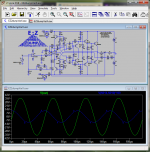
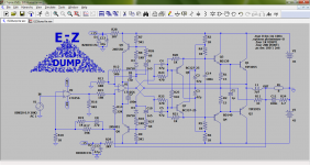
The speed-up cap seems enough for Minek's models but not enough for LVs. But I found another "solution". Ie put some voltage on the collectors of Q7,8 by moving them to the bootstrap voltage. To avoid early effect? I avoided going directly to the rails due to the limited voltage capability of Q7,8. Another possibility is use the op-amp voltages.
This seems to happen when Q1 stops conducting and the revision of R1,2,11 and caps works well.
Attachments
Last edited:
They are not going to be very accurate.... but 20 years ago, the situation was no better.And another questions is how the actual transistors from Mouser gonna
differ from spice models defined 20 years ago..
The vast majority of models are heavily inaccurate, overly simplified or plain wrong.
Many parameters are not used, or defaulted, or just have some silly convenient value. For example, many transistor models from Moto/Onsemi have Vaf=100V, which is not believable.
Most models work reasonably well in simple, "normal" situations though, but as soon as you begin to scratch the surface, you find discrepancies.
Sims should just be a confirmation for a circuit designed in a deterministic way, and if it doesn't behave the way it is expected to, they can draw the attention of the designer to an overlooked issue, but sometimes the sim malfunction cannot be traced to a precise, objective cause, like here.
The circuit is unusual, uses positive and negative feedback and bootstrapped opamp rails, which all are touchy issues for simulators, especially the bootstrapped rails.
Sometimes, changing the order of two series components has a huge impact, when it shouldn't of course.
Even "improved" models like Cordell's ones have problems of their own.
In such a situation, the only way to obtain definitive answers is to build the circuit, but you have been warned: a purely virtual design will practically always need some debugging when it is actually built, even if the sim works perfectly.
If you feel it is too risky, you can wait a few months: I will certainly build the circuit
I see that using sims with the same models can be useful in COMPARING results for different amps.Most models work reasonably well in simple, "normal" situations though, but as soon as you begin to scratch the surface, you find discrepancies.
...
If you feel it is too risky, you can wait a few months: I will certainly build the circuit
Different schematic + same models.
Perhaps that's why you are always using BD139/BD140/2N3055 models
")
Simulation seems useless to obtain hard numbers (such as THD), these can be only reliably measured in real circuit.
PCB is already in the making, I have all the parts in stock (only had to order ZTX drivers), so I'm definitely going to try to build it when PCB is ready. Even if 1st build is wasted, there will be 2nd one.If you feel it is too risky, you can wait a few months: I will certainly build the circuit
As irrational as it might be, I don't build amps because I "need an amp", but for fun of building..
If you are planning to build it, let me know (via PM) if you are interested in free PCBs; once they arrive, I can mail it you. I'll have 10 of them.
Minek, I finally assembled a quick and dirty prototype to have definitive answers.
As could be expected, some debugging work will be needed on the physical version, and as expected too, the problems encountered in the real world bear little resemblance with the sim, thus it will take some time to sort things out.
It would be a good idea to put your project on hold, if it is still possible
OK!Minek, I finally assembled a quick and dirty prototype to have definitive answers.
As could be expected, some debugging work will be needed on the physical version, and as expected too, the problems encountered in the real world bear little resemblance with the sim, thus it will take some time to sort things out.
It would be a good idea to put your project on hold, if it is still possible
- Home
- Amplifiers
- Solid State
- EZ-Dump: dump your current without really trying