I have one of these DACs, but I got it without transformer. I have a 15-0-15 transformer, but I don't have an 8v handy.
Could I stick 12V DC into the 0-8 inputs? 8VAC would rectify to about 11V DC anyway. Seems like it would pass right through the diodes and caps and come out the same in the end, but maybe there is something I'm not considering.
Could I stick 12V DC into the 0-8 inputs? 8VAC would rectify to about 11V DC anyway. Seems like it would pass right through the diodes and caps and come out the same in the end, but maybe there is something I'm not considering.
Lundahls have winding resistance about 9 ohms, it's deadly heavy load for DAC outputs. Almost a short. I decided not to try Lundahls. But I have another idea which I must try. I'll post the results.
Does this involve the Lundahls or should I not bother with them?
Here's an LL1517 output circuit I came across reportedly good sounding from a Calrec mixing desk -
It drives the transformer with the rated negative source impedance -18ohm
How would/any point in trying to mod this to balanced operation?
Last edited:
Wushuliu, if that 220V line has continuity with the other mains lines, then it has mains going through it and must be insulated. I'd cut it right back and the tape the stump.
Definitely will. Don't feel comfortable with it just dangling there...

Where to find C22, C23 and R2
I bought this DAC two months ago.
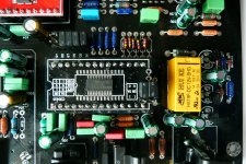
I would like to check the values of C22, C23 and R3 and if needed change them to the updated values given by Cirrus.
However, I do not have a schematic (Mr. Chan says he has none), and I really don't know where they are located on the pcb.
Could someone point them out on the enclosed picture (I guess they should be close to the CS8416)?
I would be really grateful!
Regards,
Lucas
I bought this DAC two months ago.
I would like to check the values of C22, C23 and R3 and if needed change them to the updated values given by Cirrus.
However, I do not have a schematic (Mr. Chan says he has none
), and I really don't know where they are located on the pcb.Could someone point them out on the enclosed picture (I guess they should be close to the CS8416)?
I would be really grateful!
Regards,
Lucas
Attachments
Yes, I could do this, but I'm madly busy now. You must be patient.
Thanks Mc. When you get the time could you check this link - i believe that's what you are using (linked page is in croatian but understandable). What else do I need (resistors, capacitors...)?
Again, thx.
Does this involve the Lundahls or should I not bother with them?
Here's an LL1517 output circuit I came across reportedly good sounding from a Calrec mixing desk -
It drives the transformer with the rated negative source impedance -18ohm
How would/any point in trying to mod this to balanced operation?
An externally hosted image should be here but it was not working when we last tested it.
The transformers used to be attached to the DAC in order to completely get rid with opamps, so I don't like that idea.
Thanks Mc. When you get the time could you check this link - i believe that's what you are using (linked page is in croatian but understandable). What else do I need (resistors, capacitors...)?
Again, thx.
I can see no link to check.
@McGyver: As I see on your webpage, monacors are connected directly to DAC and after to tube output. If I go "monacors only" route, without tube, what do I need to do (resistors?/capacitors?)? Or is it just that simple - monacors only and thats it? Could it be that simple?
Can I ask some fundamental questions here - I've tried to read all the thread or search for answers but drawn a blank.
I'm following this for information about using output transformers on a differential voltage out DAC - in my case it's a PCM1793 DAC with a min output impedance of 1,7K.
In order to experiment with different transformers, I need to understand some of the transformer connections and surrounding components.
First, I'm using transformers with centre tapped primaries & secondaries. I'm confused about whether to connect the centre-tap of the primary to the DAC ground? Do I connect the centre tap of the secondary to the next stage ground? Do I connect the ground straight through? My guess is I don't connect the primary or secondary centre taps to anything but I do connect the DAC ground staright through to the next stage ground?
I understand the function of the Low Pass Filter so I used a series resistor 3.3K (above the min 1.7K) on each differential leg and a 470pF capacitor across both legs to give a cut-off frequency of 102KHz.
What is the function of the resistor across the secondaries?
I've tried a couple of configurations - with some I get hum but resolved by connecting the ground straight through. Sound was low on a 1:1 transformer (200ohm impedance on 1 primary, so 400ohm across the primaries) so I had a 1:7 transformer (59 ohm on 1 primary & 710 ohm on 1 secandary) I tried thinking it would give me gain but in fact it was lower in volume. What am I missing?
Last edited:
First, I'm using transformers with centre tapped primaries & secondaries. I'm confused about whether to connect the centre-tap of the primary to the DAC ground? Do I connect the centre tap of the secondary to the next stage ground? Do I connect the ground straight through? My guess is I don't connect the primary or secondary centre taps to anything but I do connect the DAC ground staright through to the next stage ground?
But what happens to the + & - from the secondaries? I thought one of these would act as the ground for the next device (preamp or amp)?
Can I ask some fundamental questions here - I've tried to read all the thread or search for answers but drawn a blank.
I'm following this for information about using output transformers on a differential voltage out DAC - in my case it's a PCM1793 DAC with a min output impedance of 1,7K.
In order to experiment with different transformers, I need to understand some of the transformer connections and surrounding components.
First, I'm using transformers with centre tapped primaries & secondaries. I'm confused about whether to connect the centre-tap of the primary to the DAC ground? Do I connect the centre tap of the secondary to the next stage ground? Do I connect the ground straight through? My guess is I don't connect the primary or secondary centre taps to anything but I do connect the DAC ground staright through to the next stage ground?
I understand the function of the Low Pass Filter so I used a series resistor 3.3K (above the min 1.7K) on each differential leg and a 470pF capacitor across both legs to give a cut-off frequency of 102KHz.
What is the function of the resistor across the secondaries?
I've tried a couple of configurations - with some I get hum but resolved by connecting the ground straight through. Sound was low on a 1:1 transformer (200ohm impedance on 1 primary, so 400ohm across the primaries) so I had a 1:7 transformer (59 ohm on 1 primary & 710 ohm on 1 secandary) I tried thinking it would give me gain but in fact it was lower in volume. What am I missing?
You're not asking fundamental questions at all, you should be asking what a differential output is, because you dont use grounds in a differential circuit.
The plus and minus are mirror images of each other and no ground reference is needed unless you are feeding a single ended preamp, which requires you to connect either the plus or minus output of the trafo to the shield of the RCA jacks, and either will do, the trafos don't care.
Use the minimum series resistance that your dac chip can handle,any more and you are just throwing away signal.
The resistor or RC filter on the secondaries is not for I/V, it's for supressing the inherent ringing in the trafos and nothing else. A resistor alone will greatly affect the load the DAC chip sees, most use an RC filter.
If you have hum you should be looking elsewhere for the cause unless you have something very miswired.
Best, Bill
Please!
I sincerely hope someone knows where to find these 3 parts. I have read this entire thread, but I could not find a clue as to their geographical positions. The pcb does not mention the names of the parts, only the values and those are hidden under the parts...
If it is too much trouble to mark them on the photo that I included, maybe someone can describe their location...
BTW, thank you all for all the valuable info in this thread! With this knowledge we can get much more out of this DAC!
I bought this DAC two months ago.
I would like to check the values of C22, C23 and R3 and if needed change them to the updated values given by Cirrus.
However, I do not have a schematic (Mr. Chan says he has none
Could someone point them out on the enclosed picture (I guess they should be close to the CS8416)?
I would be really grateful!
Regards,
Lucas
I sincerely hope someone knows where to find these 3 parts. I have read this entire thread, but I could not find a clue as to their geographical positions. The pcb does not mention the names of the parts, only the values and those are hidden under the parts...
If it is too much trouble to mark them on the photo that I included, maybe someone can describe their location...
BTW, thank you all for all the valuable info in this thread! With this knowledge we can get much more out of this DAC!
You're not asking fundamental questions at all, you should be asking what a differential output is, because you dont use grounds in a differential circuit.
The plus and minus are mirror images of each other and no ground reference is needed unless you are feeding a single ended preamp, which requires you to connect either the plus or minus output of the trafo to the shield of the RCA jacks, and either will do, the trafos don't care.
Use the minimum series resistance that your dac chip can handle,any more and you are just throwing away signal.
The resistor or RC filter on the secondaries is not for I/V, it's for supressing the inherent ringing in the trafos and nothing else. A resistor alone will greatly affect the load the DAC chip sees, most use an RC filter.
If you have hum you should be looking elsewhere for the cause unless you have something very miswired.
Best, Bill
Thanks Bill,
I understood the differential signals but also was confused about the ground & I had hum issues which went away when the ground was connected
So, I have used a 3K series R on each Primary leg and the DAC min impedance is 1.7K - this is what I should reduce it to for less signal loss.
I should use an RC across the the secondary to reduce ringing but this requires a scope & signal generator. I have a scope but no sig gen - I can use a PC program, Audacity/Goldwave - what do I need to gen, a square wave?
I'll try to track down the hum with this new information.
Also, I could just experiment with using a cap instead of a transformer!
Last edited:
Thanks Bill,
I understood the differential signals but also was confused about the ground & I had hum issues which went away when the ground was connected
So, I have used a 3K series R on each Primary leg and the DAC min impedance is 1.7K - this is what I should reduce it to for less signal loss.
I should use an RC across the the secondary to reduce ringing but this requires a scope & signal generator. I have a scope but no sig gen - I can use a PC program, Audacity/Goldwave - what do I need to gen, a square wave?
I'll try to track down the hum with this new information.
Also, I could just experiment with using a cap instead of a transformer!
I'm not familiar with the 1793, you might possibly need a step up trafo if the output voltage is lower than most chips, but you should still have a clean, quiet signal. I would not be afraid of using 1K on each leg in a pure differential arrangement as long as there is no return to ground.
Yes, a square wave is what to use, and a PC program will work fine. Many trafo manufacturers publish their specs with the resonant frequency stated but most don't. I would pick a freq out of the audio band as you have done on the primaries. Jensen uses 150Khz on some of theirs which is around 1K in series with .1uf right across the secondaries. I have a scope and gen and I experimented with several trafos and found that the 1K/.1uf combo worked fine with all of them. I don't listen to square waves so I lost all concern with finding the exact setup needed, it's not audible to me.
Many people feel the need to place a load across the secondaries but after reading the white papers from the manufacturers I have found this to be totally untrue, except in the case of high impedence trafos of 10K or so.
Some are using their DACs with just caps but be aware that any high freq noise present will be entering your system and could possibly cause major damage, depending on your equipment.
Best regards, Bill
I'm not familiar with the 1793, you might possibly need a step up trafo if the output voltage is lower than most chips, but you should still have a clean, quiet signal. I would not be afraid of using 1K on each leg in a pure differential arrangement as long as there is no return to ground.
The 1793 has a voltage out of 3.2 Vp-p and this is followed by a LPF & balanced gain stage based on OP275 op-amp, giving 77KHz cut-off & 1.83 gain to bring the voltage up to 5.9 Vp-p or 2.1 Vrms.
I'm not sure what you mean by no return to ground?
I guess I could bring down the LPF to about 70KHz as in the datasheet!Some are using their DACs with just caps but be aware that any high freq noise present will be entering your system and could possibly cause major damage, depending on your equipment.
Yes, a square wave is what to use, and a PC program will work fine. Many trafo manufacturers publish their specs with the resonant frequency stated but most don't. I would pick a freq out of the audio band as you have done on the primaries. Jensen uses 150Khz on some of theirs which is around 1K in series with .1uf right across the secondaries. I have a scope and gen and I experimented with several trafos and found that the 1K/.1uf combo worked fine with all of them. I don't listen to square waves so I lost all concern with finding the exact setup needed, it's not audible to me.
Many people feel the need to place a load across the secondaries but after reading the white papers from the manufacturers I have found this to be totally untrue, except in the case of high impedence trafos of 10K or so.
Best regards, Bill
So if I put a R across the secondary legs, this is reflected back to the primary and seen by the DAC's output? What is the formula for that, if my trafo is 1:7.
- Home
- Source & Line
- Digital Line Level
- Experience with this DIY DAC ?