Maybe prairiemystic can add the mods to his excellent schematic?
would be great
")
Has anyone questioned this DAC's output (reconstruction) filter?
It's quite different from Cirrus CS4398 datasheets and the values look weird for a 2-pole differential filter
Yes, I'm pretty sure it's been questioned a few times. Don't know how it answered.
Seriously, though, I think that has been addressed in this thread and possibly others and you are correct, the frequency response is less than optimal. Somebody posted a schematic which I might have saved had I not already decided to move to transformers. It might actually be faster just to redesign the think than to dig through bazillions of posts.Jim
Last edited:
Okay, I'll put the mods that worked for me on the schematic, just have to find a way to draw that as it's a pretty cluttered drawing. I want to fix up the O/P filter first and will simulate it. I drew the "stock" schematic, so all jumpers are what I found.
Thank you
Woot! Ran two wires from neg secondary of each OT to the ground hole from the original RCA output jacks and hum is instantly gone! Dead silent. Thanks everyone, and I hope this ends up being useful to someone else.
Oh one small thing: when I power down (it's in a switched preamp power input in a tube system) with the volume up I get some serious spacey / theramin sounds as the amp dies. Doesn't affect listening just wondering why that would be?
Thanks again!
Could you please explain in detail how you did it? Which one is "neg secondary"? One of the pins connected to output or?
I'm using this transformer:
http://www.google.hr/url?sa=t&source=web&cd=3&ved=0CB8QFjAC&url=http%3A%2F%2Fwww.monacor.dk%2Fprodukter%2Fproflyd-linedriver%2Fvnr%2F210500%2F%3Ftype%3D257%26no_cache%3D1&rct=j&q=Monacor%20LTR-110&ei=aCiJTYavO87esgb2__S9DA&usg=AFQjCNHbZbxw-6v9I87KDrlf1S7TTyDUZw&cad=rja
thx
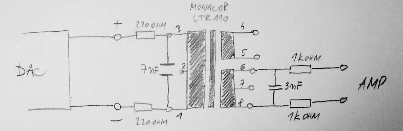
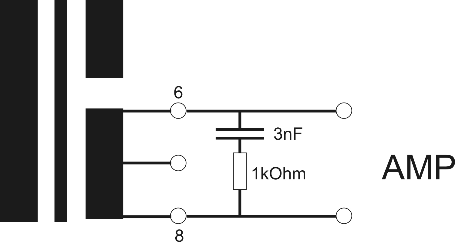
Maybe I should clarify, this is schematic of the Monacor LTR-110 audio line transformer...output lines are conected to pins 8 and 6...I hear buzz when DAC is connected and turned on, it is posible to hear it when no musical signal is being played, with volume turned up halfway on (2x50W) amplifier. If music is playing, buzz cannot be detected since it's allways significantly quieter than the music signal.
Attachments
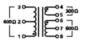
This is what promo material has to say:
"Audio transformer 1:1/2:1 for line signals
• Unshielded version with print connections
• Wideband version
• Change from unbalanced to balanced and vice versa
• Galvanic isolation to avoid/eliminate hum loops
• Various level adjustment possibilities when windings are arranged accordingly
When installing unshielded transformers into units with interference fields (e.g. power transformers), attention
has to be paid to respective shielding measures.
Technical data:
Frequency range : 15-30,000Hz
Transformation ratio : 1:1/2:1
Input impedance : 600 Ohm
Output impedance : 600 Ohm/300 Ohm
Optimum source imped. : 50-600 Ohm
Optimum load imped. : ≥ 5k Ohm
Max. input voltage (1%
THD/40Hz)
: 5V
Dimensions : 25x19x19.5mm
Weight : 28g"
Trafos are connected as per Legarem/Gerarda advice...
input side...please ignore the output side, it's wrong...
http://www.diyaudio.com/forums/atta...82d1254231813-experience-diy-dac-dsc00926.jpg
output side...
http://www.diyaudio.com/forums/atta...2458d1254309555-experience-diy-dac-filter.jpg
Have you tried moving them? There's nothing wrong with your wiring. You can also move your power trafo.
I'll try,...thought of that, but unfortunatelly, I allready glued them to the board, so I'll have to be extra carefull, they are tiny...
They are allready as far from power trafo as board would allow (cca 15cm)...
BTW, how should one go about shielding them?
What I did not understand in few previous posts about grounding the output (audio) trafos is which leg I should ground? Edit: in post #3715...
And one more question: power trafo was taken from old CD player - I remember that at some point there was connection to the metal chassis, but I think it was from the internal PCB, not the trafo. Anyway, trafo has original two prong connector without grounding...and I don't know if maybe I should ground trafo chassis or something...I know, this is really not my forte, I should do some serious Electronics basics learning...
Last edited:
If you're going to ground an output leg, ground the one that's connected to the RCA shell, naturally.
The chassis should ideally be connected directly to the house ground for safety, and a bit of shielding. You could use a steel partition to help shield the OP trafos from the power trafo if that is where the problem is.
The chassis should ideally be connected directly to the house ground for safety, and a bit of shielding. You could use a steel partition to help shield the OP trafos from the power trafo if that is where the problem is.
If you're going to ground an output leg, ground the one that's connected to the RCA shell, naturally.
The chassis should ideally be connected directly to the house ground for safety, and a bit of shielding. You could use a steel partition to help shield the OP trafos from the power trafo if that is where the problem is.
Thank you, I'll try that.
Well, it turns out it was power transformer problem. I was confused because when I assembled dac/trafo for the first time I did try different orientations but since I did not turn the volume all the way, i did not hear the buzz...it's only after the halfway that it becomes audible...so now I maxed out the pot, rotated power trafo around two different axis and also moved it a bit farther from the monacors...all is well and allmost completely silent at max pot position...
thx again, Bill
thx again, Bill
I didn't find anything counterfeit on these boards
All parts measure as they should. Only the small Elna electrolytics (10-470uF) were poor performers (like all Chinese capacitors nowadays) having high ESR and leakage- the kind that last a couple years max.
I notice the passives and most semi's have date codes from 1992-1999. So I have to wonder where they've been hiding for the past decade. The CS4398 is 2009 and the CS8416 is 2010. The "no name" mylar caps match my Epcos parts sans laser etching.
Could you describe the mod more closely?cap mod by prairiemystic works well.
Could you describe the mod more closely?
Read the whole description at post #3865
I only did 2.2uF cap mod only
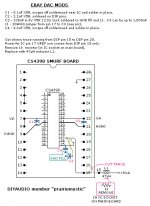
My mods to the CS4398 smurf board
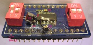
Here's the schematic+pic of basic first mods I've done to the DAC. They are high risk to wrecking your CS4398 daughter board, due to the low pcb quality... and wouldn't win any beauty contest, lol.
It's mainly adding SMT ceramic decoupling caps close to the IC pins. I found these have huge improvements to the DAC's sound; I also used a 'scope to verify noise and ripple.
I haven't optimized the caps; C3 (on VREF) needs to be low ESR and easily 820-1,000uF before the VREF signal gets clean DC. Cirrus used 1,000uF to keep their distortion curves flat on the low end (<100Hz). This VREF pin is really demanding and sound quality changes a lot with cap type and lead lengths. I think next would be to drive the pin with an op-amp buffer.
I got ticked off at the traces lifting so I laid out my own version (smurf) pcb with proper ground fill and thick traces, but they're not in yet.
Attachments
Here's the schematic+pic of basic first mods I've done to the DAC. They are high risk to wrecking your CS4398 daughter board, due to the low pcb quality... and wouldn't win any beauty contest, lol.
It's mainly adding SMT ceramic decoupling caps close to the IC pins. I found these have huge improvements to the DAC's sound; I also used a 'scope to verify noise and ripple.
I haven't optimized the caps; C3 (on VREF) needs to be low ESR and easily 820-1,000uF before the VREF signal gets clean DC. Cirrus used 1,000uF to keep their distortion curves flat on the low end (<100Hz). This VREF pin is really demanding and sound quality changes a lot with cap type and lead lengths. I think next would be to drive the pin with an op-amp buffer.
I got ticked off at the traces lifting so I laid out my own version (smurf) pcb with proper ground fill and thick traces, but they're not in yet.
prairiemystic
why do you ground C4 & C3 to other grounding? Aren't it be easier to ground the caps to pin 16 (REF_GND) ground ref....
C4 rating is 6.3V for SMD, where else max V for 4398 is 5V, is it safe to do this???? What's the different if I choose radial type of X5R which has bigger V rating....or maybe a film type....???
For inductors, C1 & C2 mod is this worth while to do if you already have a linear psu for the dac?
Last edited:
- Home
- Source & Line
- Digital Line Level
- Experience with this DIY DAC ?