OK, so for those wishing to implement the 'Op-Amp' mod - using an LM4562, these are the steps involved (please jump in anyone if there's any obvious mistakes!) :
1) Remove both NE5532s. Insert one (only) LM4562 in the first op-amp socket - the one nearest the center of the board.
2) Remove the following 4 capacitors: L+ / L- / R+ / R-. Replace with wire links.
3) Replace R14, and R17 (both 22k) with 36k.
4) Run a wire directly from the output pins (1 and 7) of the LM4562s to the phono sockets (via the output rely if you prefer this added safety measure).
- John
Hey guys! I made this mod, but i didnt found R14 and R17 on board! Can somebody help me? After removing L+ / L- / R+ / R- capacitors i hear a very big distortion! (at the attached picture not shown, but i shorted 4 capacitors links)
Attachments
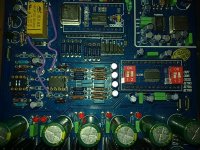
Hey guys! I made this mod, but i didnt found R14 and R17 on board! Can somebody help me? After removing L+ / L- / R+ / R- capacitors i hear a very big distortion! (at the attached picture not shown, but i shorted 4 capacitors links)
Check the photo.... You have links in place of 1 k resistors which is most likely the reason for distortion.
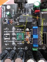
Remove all parts that are not needed and bring ALL the tracks to ground potential
Feed the signals from Out1 and Out2 to relay pins 13 and 4 respectively.
NOTE: my arrows point to the relay coils - that is a mistake!!!
Cut the tracks around pins 13 and 4. The remaining coper should be brought to ground potential
What I haven't shown is the wires underneath connecting Out1 and Out2 to relay pins 13 and 4... various IC’s will require careful routing and / or series resistors…
DC level at the output is less than 4 mV with good IC....
For the proper symmetry (high frequency attenuation on both halves of balanced signals coming from the DAC), the capacitors should be matched as per my photo; 4 X 1nF and 4 X 100 - 200pF (choose the value between 100 to 200pF…. that suits your taste and your system. I use 4 X 150pF). Use FKP2 if possible. The cost of this DAC (with mods shown) is around $130 and that’s with the mains transformer included in price – truly unbelievable… the mods shown will give you very good sound.
Installed in nice box (another $100), this DAC with the mod shown will easily match $1000 - $1500 commercial DAC's...
Boky
Attachments
which dac chip?
Which dac chip do you use?
DC level at the output is less than 4 mV with good IC....
Boky
Which dac chip do you use?
coupling caps
Does it sound ok with caps back in instead of links at L+ / L-/ R+ / R-? How much dc is on the RCAs?
Hey guys! I made this mod, but i didnt found R14 and R17 on board! Can somebody help me? After removing L+ / L- / R+ / R- capacitors i hear a very big distortion! (at the attached picture not shown, but i shorted 4 capacitors links)
Does it sound ok with caps back in instead of links at L+ / L-/ R+ / R-? How much dc is on the RCAs?
coupling caps
")
I will try today at night and reply! ThanksDoes it sound ok with caps back in instead of links at L+ / L-/ R+ / R-? How much dc is on the RCAs?
ok
ok. I will have to try to figure out why my upsampler won't work with the 9001.
DIR9001-CS8421-CS4398.
ok. I will have to try to figure out why my upsampler won't work with the 9001.
Yes, if i remove links, all works ok. DC in both situations is about 10mV. I think, electrolythic capacitors in signal line is not very good for sound, maybe just replace them with film caps?Does it sound ok with caps back in instead of links at L+ / L-/ R+ / R-? How much dc is on the RCAs?
Does it sound ok with caps back in instead of links at L+ / L-/ R+ / R-? How much dc is on the RCAs?
Yes, after removing links it sounds OK. DC in both situations is about 10 mV. Maybe just replace caps with film caps? (i think electrolythic caps in signal path is not the best thing)
I've spent some time trying to get absolute best from this DAC for bare minimum spent in parts; I found interesting thing while minimising noise on Vcc / Vss pins....the only DAC chip that will give some reasonable results is in fact 4397 - all other plug in modules are seriously compromised...
Boky
Boky
Hi,
I connected two Jensen JT-11-EMCF at the output of the DAC and the sound is absolutely phantastic. At the moment i have two 500K resistors and one 1nF before the transformer and one 1k + 1nF after the transformer.
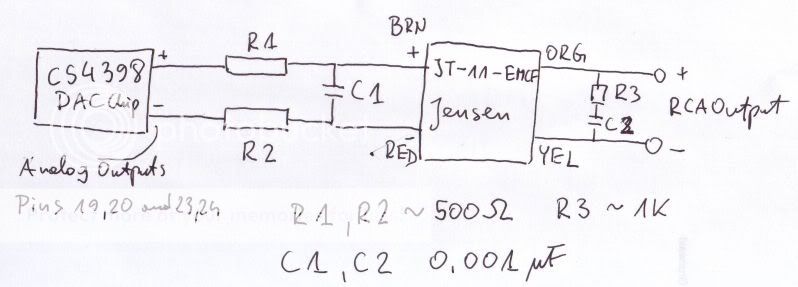
The bass and dynamic is weaker than with opamps. Should i try bigger or smaller resistors before Jensens if i want to have better bass and dynamic ?
Second question - the usb part is disabled - ps cap & lm317 for usb is cut out. The +15,0,-15V for the anogue power is no more connected. Should i remove the four small electrolyt caps at the output of the dac, or can i leave them in place ?
I connected two Jensen JT-11-EMCF at the output of the DAC and the sound is absolutely phantastic. At the moment i have two 500K resistors and one 1nF before the transformer and one 1k + 1nF after the transformer.
The bass and dynamic is weaker than with opamps. Should i try bigger or smaller resistors before Jensens if i want to have better bass and dynamic ?
Second question - the usb part is disabled - ps cap & lm317 for usb is cut out. The +15,0,-15V for the anogue power is no more connected. Should i remove the four small electrolyt caps at the output of the dac, or can i leave them in place ?
Drop R1-2 down to 200 ohms or so.
I don't know exactly what you have left in the original output circuit, you can pull the caps if you are careful, or pull the resistors that follow them. Leaving them in place should be OK as long as there is no path to ground through anything else.
I don't know exactly what you have left in the original output circuit, you can pull the caps if you are careful, or pull the resistors that follow them. Leaving them in place should be OK as long as there is no path to ground through anything else.
- Home
- Source & Line
- Digital Line Level
- Experience with this DIY DAC ?