CS4398 vs PCM1794
I´ll try to describe it in short words.
CS4398 Rock n´roll PCM1794 HiFi.
CS 4398 is, at the moment more fun to listen to,I wish I could use both in my case with it´s own RCA output..
I´ll listen some more...
Edit:Anyone else that have some listening impressions between the two?
I´ll try to describe it in short words.
CS4398 Rock n´roll PCM1794 HiFi.
CS 4398 is, at the moment more fun to listen to,I wish I could use both in my case with it´s own RCA output..
I´ll listen some more...
Edit:Anyone else that have some listening impressions between the two?
PCM1798 vs CS43122 vs AK4395
My cheap steel core trannies may be playing a part in my results but I am finding the PCM1798 with trans I/V and 40 ohms load at 1:8 is smooth and musical but lacks some fine resolution compared to a direct out CS43122 which also beats my long time standby, the AK4395. I am still planning to try the PCM1794a in mono mode when I get a chance to order the parts to go on my blank module boards and can then also order some header pins to plug the Opus dac (Wolfson) into the big dac board.
CS4398 vs PCM1794
I´ll try to describe it in short words.
CS4398 Rock n´roll PCM1794 HiFi.
CS 4398 is, at the moment more fun to listen to,I wish I could use both in my case with it´s own RCA output..
I´ll listen some more...
Edit:Anyone else that have some listening impressions between the two?
My cheap steel core trannies may be playing a part in my results but I am finding the PCM1798 with trans I/V and 40 ohms load at 1:8 is smooth and musical but lacks some fine resolution compared to a direct out CS43122 which also beats my long time standby, the AK4395. I am still planning to try the PCM1794a in mono mode when I get a chance to order the parts to go on my blank module boards and can then also order some header pins to plug the Opus dac (Wolfson) into the big dac board.
Yes,thats what I think to,but the bas and midrange (3D) is fine.musical but lacks some fine resolution
PCM1798 vs
Here is another post that has the new owner of a small Gigawork dac and upgraded OPA627 opamps wondering if the highs of the PCM1798 are a little week.
.
http://www.diyaudio.com/forums/digi...ew-small-diy-gigawork-dac-13.html#post2345537
Yes,thats what I think to,but the bas and midrange (3D) is fine.
Here is another post that has the new owner of a small Gigawork dac and upgraded OPA627 opamps wondering if the highs of the PCM1798 are a little week.
.
http://www.diyaudio.com/forums/digi...ew-small-diy-gigawork-dac-13.html#post2345537
Here's some of my thoughts on this design:
My board had the proper CS8416 PLL filter parts on it, no need to mess with those as apparently they fixed the design somewhere in production.
My board was running the CS8421 ASRC chip at 5 volts due to them bypassing the 3.3 volt regulator on the board. This toasted my chip and I added a regulator and a new chip to the daughter board.
My board came with OPA623's on dual adapter board already so these are the only chips I've been using.
I bypassed the coupling caps all though the analog stage. I put a little piece of wire across the leads of each one. I also removed the buffer stage completely from the circuit so the analog stage is DAC -> Filter -> Relay -> RCA
Before I took delivery of this board, I had designed a DAC of my own based on the same Crystal (now Cirrus) chip set: CS8416 -> CS8421 -> CS4398. But I used Lundahl 1:1 transformers on the output stage.
My DAC sounds a lot better to my ears (probably non-objective ears though). I think the biggest difference is the transformer output stage, but my design has better signal quality (as the chips are on the circuit board instead of dip adapters), and better power supplies than this board in stock form. I'm using a better oscillator for the ASRC and the power to that oscillator is very clean due to a finesse circuit.
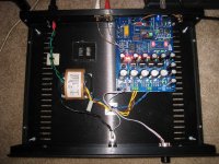
In addition to contributing throughout this thread, my DIY DAC can be seen here:
Sheldon’s World Blog Archive Another Audio Digital-to-Analog (DAC) is Born
Hope that helps.
Sheldon
My board had the proper CS8416 PLL filter parts on it, no need to mess with those as apparently they fixed the design somewhere in production.
My board was running the CS8421 ASRC chip at 5 volts due to them bypassing the 3.3 volt regulator on the board. This toasted my chip and I added a regulator and a new chip to the daughter board.
My board came with OPA623's on dual adapter board already so these are the only chips I've been using.
I bypassed the coupling caps all though the analog stage. I put a little piece of wire across the leads of each one. I also removed the buffer stage completely from the circuit so the analog stage is DAC -> Filter -> Relay -> RCA
Before I took delivery of this board, I had designed a DAC of my own based on the same Crystal (now Cirrus) chip set: CS8416 -> CS8421 -> CS4398. But I used Lundahl 1:1 transformers on the output stage.
My DAC sounds a lot better to my ears (probably non-objective ears though). I think the biggest difference is the transformer output stage, but my design has better signal quality (as the chips are on the circuit board instead of dip adapters), and better power supplies than this board in stock form. I'm using a better oscillator for the ASRC and the power to that oscillator is very clean due to a finesse circuit.
In addition to contributing throughout this thread, my DIY DAC can be seen here:
Sheldon’s World Blog Archive Another Audio Digital-to-Analog (DAC) is Born
Hope that helps.
Sheldon
Trans output
Now it would be intersting to have you install the same transformer output on the Big Dac Board in order to hear how much difference in comparison to your dac remains.
Here's some of my thoughts on this design:
My board had the proper CS8416 PLL filter parts on it, no need to mess with those as apparently they fixed the design somewhere in production.
My board was running the CS8421 ASRC chip at 5 volts due to them bypassing the 3.3 volt regulator on the board. This toasted my chip and I added a regulator and a new chip to the daughter board.
My board came with OPA623's on dual adapter board already so these are the only chips I've been using.
I bypassed the coupling caps all though the analog stage. I put a little piece of wire across the leads of each one. I also removed the buffer stage completely from the circuit so the analog stage is DAC -> Filter -> Relay -> RCA
Before I took delivery of this board, I had designed a DAC of my own based on the same Crystal (now Cirrus) chip set: CS8416 -> CS8421 -> CS4398. But I used Lundahl 1:1 transformers on the output stage.
My DAC sounds a lot better to my ears (probably non-objective ears though). I think the biggest difference is the transformer output stage, but my design has better signal quality (as the chips are on the circuit board instead of dip adapters), and better power supplies than this board in stock form. I'm using a better oscillator for the ASRC and the power to that oscillator is very clean due to a finesse circuit.
In addition to contributing throughout this thread, my DIY DAC can be seen here:
Sheldon’s World Blog Archive Another Audio Digital-to-Analog (DAC) is Born
Hope that helps.
Sheldon
Now it would be intersting to have you install the same transformer output on the Big Dac Board in order to hear how much difference in comparison to your dac remains.
NO
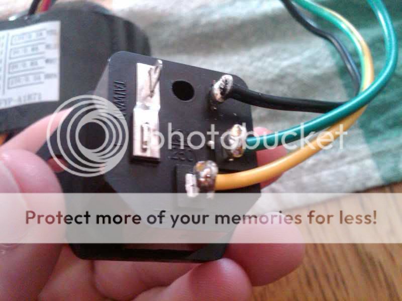
that goes through the fuse .......see the ground symbol the yellow wire in middle the of the plug ,that is the bonding to the chassis or pan you are using the other two lugs with wires say on them 10A at 250 don't TOUCH them when it's plugged in or let them touch anything those will shock you,do yourself a favor and cover them with black electrical tape,GOOD Luck,,,,you may have to set some jumpers then it will work!!!!!
that goes through the fuse .......see the ground symbol the yellow wire in middle the of the plug ,that is the bonding to the chassis or pan you are using the other two lugs with wires say on them 10A at 250 don't TOUCH them when it's plugged in or let them touch anything those will shock you,do yourself a favor and cover them with black electrical tape,GOOD Luck,,,,you may have to set some jumpers then it will work!!!!!
The L on the back of this thing, is the line inlet ground? And i Just put a metal screw into the chassis with a covered wire leading to this L and I should be okay?


NO!

That is the LIVE AC input that goes to the fuse terminal. If you connect that to the chassis ground you will be in for a world of hurt.
The AC ground is the bottom green/yellow wire.
(edit: noSmoking beat me to it)
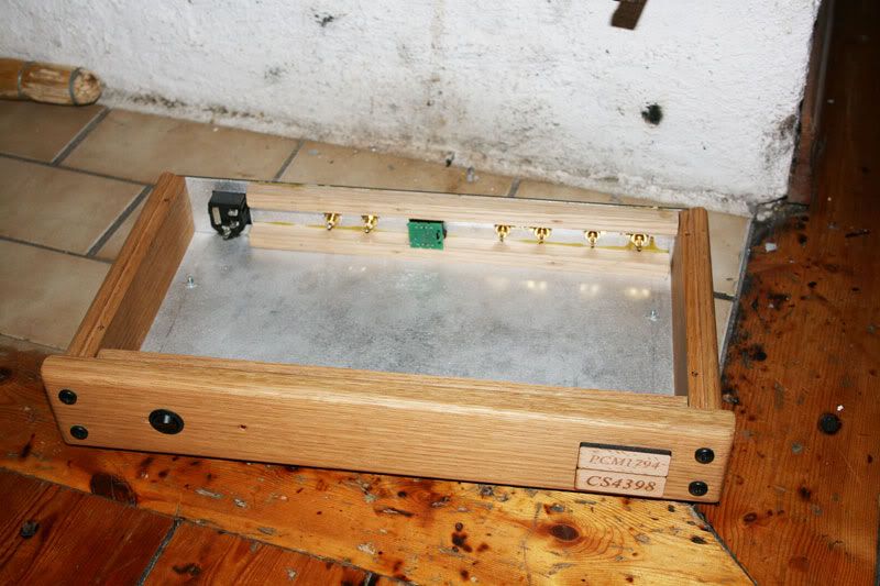
I'm going to use a picture here so I maybe get a chance to listen to this dac lol.
The L on the back of this thing, is the line inlet ground? And i Just put a metal screw into the chassis with a covered wire leading to this L and I should be okay?
The short answer to your question is NO, emphatically NO.
If you really don't know how to connect to a power inlet socket, either get some professional help or take up a safer hobby like juggling with loaded firearms.
- Home
- Source & Line
- Digital Line Level
- Experience with this DIY DAC ?