Other ideas:
- Should the voltage setting resistors (removed) for the 317's be linked out.
- Is there an issue with current, too little / too much.
-Not if you have connected the ground from the STR to the ground on the DAC board.
-No you cant "tune" the current on the STR.
Did you messaure the voltage on the CS8416?When you messaure,use the ground on the DAC board,not on the STR´s.So you´ll see that the ground is properly connected.
Well I've just ordered some new D44H11s for the STR.
I was getting 10V at STR input AND output which, according to Teddy, means they're probably fried. How that happened - I have no clue.He says it may have something to do with them not being heatsinked. Could be but I find it strange as they were only under power for a few seconds.
I was getting 5V at upsampling board "5V" pin but got 10V on CS4398 chip(pin 22) I have a spare CS4398 but will wait until I'm 110% sure everything is right before powering up.
Green leds on STRs light up as do red ones on DAC board - if that means anything.
It means there is voltage there,messaure so it´s the right voltage.Green leds on STRs light up as do red ones on DAC board - if that means anything.
Report Post Reply With Quote
-Not if you have connected the ground from the STR to the ground on the DAC board.
-No you cant "tune" the current on the STR.
Did you messaure the voltage on the CS8416?When you messaure,use the ground on the DAC board,not on the STR´s.So you´ll see that the ground is properly connected.
I always use the DAC ground when measuring.
When looking from the back of the DAC (power in end) is the right leg of the bottom blue reg resistor connected to ground? I used this for my STR ground.
Black wire in pic:
Gigawork DAC :: IMG_1902.jpg picture by RichLund - Photobucket
On the CS4398 datasheet, pin 17 is VREF which is supposed to be at 5V. I have zero volts at this pin.
However it seems that this pin is fed by one of the redundant 13V rails (first one nearest edge)
Could someone check this for me.
Do you guys have the generic schematic? It might not be exact for the different versions but it is indispensible for what you are doing.
Do you guys have the generic schematic? It might not be exact for the different versions but it is indispensible for what you are doing.
It didn't attach. New puter, having problems.
Last edited:
It didn't attach. New puter, having problems.
If anyone wants it just email me.

None of the chips are fed from 13v, don't know what that is about. All the on board regs are fed from the unregulated sources except the one on the 8421 daughter board. I'm not sure what is feeding that, it's not clear on the schematic.
Last edited:
Hi Bill
I have a Gigaworks schemetic but it shows a CS4397 chip and various others that are not on the current design DAC board. Must be an old schematic that hasn't been updated.
What is the current draw of this DAC circuit. The STR's are giving 1.5 - 2mA
Someone correct me if I'm wrong but the total draw is around 400ma for the digital chips.
The sch I have is rev5 or 6, shows all the options, 8416,dr9001, 8421,4397, 4398,etc
I seem to be getting rather confused over the positions of the switches on the DAC with regards to how they should be set when the upsampling board is fitted.
The illustration that came on the CD with the DAC shows the switches in the same position when the upsampling board is or isn't fitted. Surely this isn't correct?
To add to my confusion I've just realised the labelling on the switches actually says 'no' and not 'on'. I'm loathe to mess around with these switches; how should they be set with the upsampling board fitted please?
With the lettering facing you, from left to right, up, down, down, down.
The labelling is confusing,the switches are actually off, on, on, on.
The switches are different without the upsampling, off the top of my head, up down up up, but I may be wrong on that
The labelling is confusing,the switches are actually off, on, on, on.
The switches are different without the upsampling, off the top of my head, up down up up, but I may be wrong on that
Last edited:
I did messaure de currentdraw,one of the regs have to supply about 100-120mA and one one about 70-8mA don´t remembre exact,but it´s in that range.What is the current draw of this DAC circuit. The STR's are giving 1.5 - 2mA
Doesn´t the STR give more than 1,5-2mA?
Yeah, i read the specs wrong. That's the current source. Depending on the devices it should be around 2A
quote from Teddy:
"A 2SK363BL has a current limit of about 12mA, and the D44H11 has a hfe of about 200, the combination of the two allows a maximum current of around 2.5A. The D44H11 can withstand up to 10A and 50W so in practice the circuit is protected against short circuits at the output (I have tried it...). Note however that using jfets with higher Idss will allow higher currents."
With the lettering facing you, from left to right, up, down, down, down.
The labelling is confusing,the switches are actually off, on, on, on.
The switches are different without the upsampling, off the top of my head, up down up up, but I may be wrong on that
Thanks Bill, I'll give it a try! Shame the documentation isn't a bit clearer.
With the lettering facing you, from left to right, up, down, down, down.
The labelling is confusing,the switches are actually off, on, on, on.
The switches are different without the upsampling, off the top of my head, up down up up, but I may be wrong on that
Here are the two photos supplied with the DAC to illustrate how to set the switches -
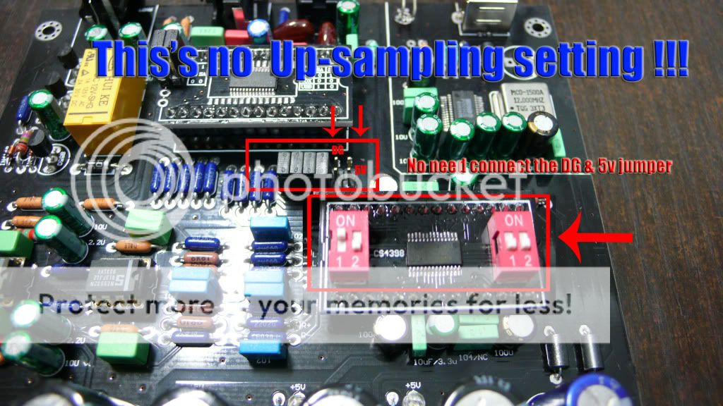
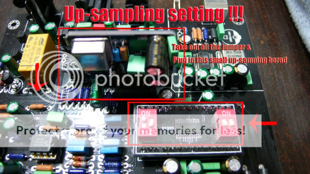
Confusing, isn't it?
I've now fitted the upsampling board with the switches set as per the photo(s) - sounds OK. I'm using an iMac as source with digital output set to 24/48.
Can somebody send me the schematic for this DAC? I'm about to buy one and replace the analog stage with a pair of Lundahl transformers.
BTW, I have been working on my own design for a cs8416-cs8421-cs4398 DAC when I stumbled on this thread. IT's hard to argue with what looks to be a very tidy design for like $125.
As a note, you can get this DAC in a reasonably nice looking enclosure for <$250 if you email the seller.
Thanks,
Sheldon
stokes@quadesl.com
Hi Sheldon
I've just uploaded the schematic for someone else to see:
CS4398 DAC2 192KHz.pdf
BTW interesting site you have.
I've just uploaded the schematic for someone else to see:
CS4398 DAC2 192KHz.pdf
BTW interesting site you have.
Last edited:
Another update to the STR problem. I found this info on a PFM thread regarding regs in DAC's:
"And you have to watch the start-up times are very close, because many bitstream dacs will lock-up if the various rails do not remains sufficiently close at start-up. Check the small print of datasheet, it may mention that rails have to remain within, typically, 0.6v."
So we need to set our regs very carefully and taking our time watching the outputs. I am looking into using a fixed resistor instead of the trimmer to set the Vout. Maybe this will give a better parity between reg outputs.
- Home
- Source & Line
- Digital Line Level
- Experience with this DIY DAC ?