I only tried it to see if it worked, I dont use the puter for music. It recognized it no problem, don't remember if I had to change any settings. I'm old and not going to change. I have a few cd transports I experiment with, great fun. At some point I'll get another dac board and try i2s directly to the 8421 chip, that will eliminate all the SPDIF conversion crap.
If anyone wants the manual with schematic email me and I'll send you the pdf.
If anyone wants the manual with schematic email me and I'll send you the pdf.
As far as mods, the field is wide open. Some are just getting around to PS mods.
As far as the output level and interfacing, if low impedence (600ohm) output trafos are used, a 10k pot will work fine. If 10k trafos are used then you might have trouble using any pot, your amp input impedence must be very high, such as a tube amp or jfet front end. In any case, use short interconnects, there isn't a lot of current available.
Uh-oh, I intend to use the Edcor 10ks I ordered to a B1 Buffer --> low input impedance amp. Is this going to be a problem?
If u look on the DAC from the connectors side there are the 6 pins
1 2 3
4 5 6
and u have to connect 5 and 6 with a jumper
1 2 3
4 5-6
The rest doesnt need any connections.
edit: oh, I didnt see the new posts. sorry..
edit2:
The dac should be automatically be recognized as an USB Audio Device. It is using standard-drivers that come with windows.
The only thing that you have to change is the standard-output-device in the systems settings. the player-software is usually using the standard-out-device for output.
If this doesnt help you also have the settings in your player-software. its the same procedure like in the systems settings.
1 2 3
4 5 6
and u have to connect 5 and 6 with a jumper
1 2 3
4 5-6
The rest doesnt need any connections.
edit: oh, I didnt see the new posts. sorry..
edit2:
The dac should be automatically be recognized as an USB Audio Device. It is using standard-drivers that come with windows.
The only thing that you have to change is the standard-output-device in the systems settings. the player-software is usually using the standard-out-device for output.
If this doesnt help you also have the settings in your player-software. its the same procedure like in the systems settings.
Last edited:
Uh-oh, I intend to use the Edcor 10ks I ordered to a B1 Buffer --> low input impedance amp. Is this going to be a problem?
Just change the pot to 100k, the impedance of the b1 is in the millions.
Rich, I used a two pole/4 pos rotary switch. There is actually a 4th input available on the cs8416 but I don't need it yet.
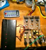
Ok thought you guys mite like to see what I've been upto? Few changes from the pix I've added a bigger regulator to the 12v rail feeding the optical inputs, just so it runs cooler.
Each main section has its own transformer winding, IE the pic has one, the control relays, and then one more for the optical converters, each optical RX also has its own 5v regulated supply fed from a 12v pre regulated supply.
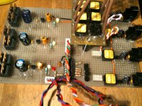
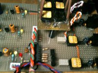
Nearly (hopefully by the end of the weekend) got the Input / output board done. The tails on the top board are for the Coax sockets the little squares are pulse transformers so as you can see every socket is isolated from each other. I'm not the best at the aesthetic work but I'd say its passable just about?
Still the power/lock led to do, this will be in the usual cyrus on/off position and will be wired to show green on signal lock and red on loss the PIC I'm using allows for a 5th infrared signal to be stored for all 4 inputs not to be selected to it will go to non lock state mute the outs and show red in off mode. Those with keen eyes will see a small switch next to the Pic this allows it to go into learn mode so you can use any remote commands you like.
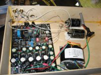
Been running it as test for a bout a week now and its working really well, so next part is the output buffer board, then I will build my own regulator section for the dac and dac subboards.
What Ya think?
It has 3 optical inputs paralleled up with 2 coax sockets each all isolated from each other and 4th input optical / usb. Reason for extra sockets is so I can pass signals to my surround for 5.1 data
Each main section has its own transformer winding, IE the pic has one, the control relays, and then one more for the optical converters, each optical RX also has its own 5v regulated supply fed from a 12v pre regulated supply.
Nearly (hopefully by the end of the weekend) got the Input / output board done. The tails on the top board are for the Coax sockets the little squares are pulse transformers so as you can see every socket is isolated from each other. I'm not the best at the aesthetic work but I'd say its passable just about?
Still the power/lock led to do, this will be in the usual cyrus on/off position and will be wired to show green on signal lock and red on loss the PIC I'm using allows for a 5th infrared signal to be stored for all 4 inputs not to be selected to it will go to non lock state mute the outs and show red in off mode. Those with keen eyes will see a small switch next to the Pic this allows it to go into learn mode so you can use any remote commands you like.
Been running it as test for a bout a week now and its working really well, so next part is the output buffer board, then I will build my own regulator section for the dac and dac subboards.
What Ya think?
It has 3 optical inputs paralleled up with 2 coax sockets each all isolated from each other and 4th input optical / usb. Reason for extra sockets is so I can pass signals to my surround for 5.1 data
Attachments
Last edited:
Actually, I am offering one of my CS4398 DAC's with Digitec trannies on eBay.
It is NOT a Gigawork DAC, but a Super Pro 707. Here in this thread, you'll find in a earlier posting this DAC.
Look here: http://www.diyaudio.com/forums/swap...c-incl-enclosure-digitec-output-trannies.html
And also a Zhaolu D3 available...
Franz
It is NOT a Gigawork DAC, but a Super Pro 707. Here in this thread, you'll find in a earlier posting this DAC.
Look here: http://www.diyaudio.com/forums/swap...c-incl-enclosure-digitec-output-trannies.html
And also a Zhaolu D3 available...
Franz
Everybody selling his stuff here now?
I am sorry: it was not my intention to spoil this thread.
Franz
hello world
if anyone interested, I sell on ebay No 140391156447 a pair of rare Transformer UTC HA-108 new, with original box, are the audio version of superpermalloy of UTC A-20, are exceptional for your dac
Starting at almost $350/pr ouch. Are they that much better than the A-20s?
Hi all,
I have the CS4397 SMD version of this DAC (CS4397 dac - The Art of Sound Forum), and from what I can determine, I should be able to implement output transformers on my DAC as per the discussion in this thread. Comparing the CS4397 to the CS4398 data sheet, the analog characteristics look similar, i.e. same load capacitance, however I can't find the output impedance of the CS4397.
Before I order the transformers, anyone know if they are not going to work with the CS4397 board?
hello world
if anyone interested, I sell on ebay No 140391156447 a pair of rare Transformer UTC HA-108 new, with original box, are the audio version of superpermalloy of UTC A-20, are exceptional for your dac
250 euro?

- Home
- Source & Line
- Digital Line Level
- Experience with this DIY DAC ?