") Excellent news.
Excellent news.
Member
Joined 2009
Paid Member


Solid power SRPP
Hi, Boys!
If you want to see a real solid state power SRPP, take a look to this link:
vetruvioaudio.com
Open the link "free schematics" in the home page and tham "Solid Power SRPP"
The circuit you will see it's a sinle stage solid state power amp operating in SRPP. The schematic is very clear and there are all the values of components.
I think it's the most simple amp of the world.
I'm gonna build it!!!
Seems good.Hi, Boys!
If you want to see a real solid state power SRPP, take a look to this link:
vetruvioaudio.com
Open the link "free schematics" in the home page and tham "Solid Power SRPP"
The circuit you will see it's a sinle stage solid state power amp operating in SRPP. The schematic is very clear and there are all the values of components.
I think it's the most simple amp of the world.
I'm gonna build it!!!
Attachments
Is the thumbnail you posted a simulation of the circuit, or it's a version already existing?Seems good.
If it is a ssimulation it cannot be good because with R1 and R2 of 47 Ohm it will never work in cass A, so it cannot be linear at all. Nether with a supply voltage of 48 Volts...
This circuit can operate only in class A with a quiscent current of 1,5 Ampere. It means that R and R2 have to be 0,47 as shown in the schematic of vetruvioaudio. This circuit dissipates 60 Watts for 10 Watts to a 8 Ohm load.
Thanks.
Is the thumbnail you posted a simulation of the circuit, or it's a version already existing?
If it is a ssimulation it cannot be good because with R1 and R2 of 47 Ohm it will never work in cass A, so it cannot be linear at all. Nether with a supply voltage of 48 Volts...
This circuit can operate only in class A with a quiscent current of 1,5 Ampere. It means that R and R2 have to be 0,47 as shown in the schematic of vetruvioaudio. This circuit dissipates 60 Watts for 10 Watts to a 8 Ohm load.
Thanks.
The value of R1 and R2 in the thumbnail is 470 mohm, equal to 0.47 ohm.
Member
Joined 2009
Paid Member
1/ Wensan - how are you enjoying your amp ? - I have started my Class A project (see SS forum) but so far I didn't propose an SRPP version. I'm still not sure that it is a good option with BJTs, the need to provide base current complicates it and I like to view SRPP as 'the simple way'. I may come back to SRPP with a JFET like the one above. What do you think ?
2/ the posting says "1.5% distortion" - even with my fondness for H2 this seems undesirable ?
2/ the posting says "1.5% distortion" - even with my fondness for H2 this seems undesirable ?
Last edited:
1/ Wensan - how are you enjoying your amp ? - I have started my Class A project (see SS forum) but so far I didn't propose an SRPP version. I'm still not sure that it is a good option with BJTs, the need to provide base current complicates it and I like to view SRPP as 'the simple way'. I may come back to SRPP with a JFET like the one above. What do you think ?
2/ the posting says "1.5% distortion" - even with my fondness for H2 this seems undesirable ?
I think the BJT SRPP with a JFET seems good.
But I will use 2SK246 instead of 2N3819.
Because the V(BR)gds is much higher.
The "1.5% distortion" is fine.
Because it is "non-feedback".
I may use it as a output stage of a power amplifier.
I think the BJT SRPP with a JFET seems good.
But I will use 2SK246 instead of 2N3819.
Because the V(BR)gds is much higher.
The "1.5% distortion" is fine.
Because it is "non-feedback".
I may use it as a output stage of a power amplifier.
Hi.
I finished to build the "Power Totem" of Vetruvioaudio the last week end:
The JFETs have to be matched (they can be very different one compared with another of the same model...) If the JFETs aren't matched, will be necessary to find the right values of R1 and R2 (very very small differences)
for to have 1/2 Vcc at 1'5 Ampere between the two Darlington.
How it sound? I don't know if 1,5 % is a big percent of distortion or not, but I know that 10 Watts in pure single ended class A with a so simple circuit and with that quality of sound, I never found before... The amp sounds always sweet, even in the most complicated transients (scales of piano or female voices). Before I used a version of JLH for listening to the music at home (I loeved it)... Now I will use the "Power Totem"...
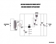
Soon I will post the schematic of the voltage regulated power supply and some photos of my "Power Totem".
This is a very attractive amp!
It looks so simple to build.
Some questions...
The capacitors values look small for a class A amp.
Aren't some resistors across the 1000uf needed to maintain half the voltage.?
Is the maximum power 25w when you are speaking of ten only?
The input signal referenced to ground isn't bringing noise?
It looks so simple to build.
Some questions...
The capacitors values look small for a class A amp.
Aren't some resistors across the 1000uf needed to maintain half the voltage.?
Is the maximum power 25w when you are speaking of ten only?
The input signal referenced to ground isn't bringing noise?
This is a very attractive amp!
It looks so simple to build.
Some questions...
The capacitors values look small for a class A amp.
Aren't some resistors across the 1000uf needed to maintain half the voltage.?
Is the maximum power 25w when you are speaking of ten only?
The input signal referenced to ground isn't bringing noise?
Hi.
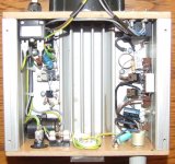
It takes 20 minutes to make all the connections of this circuit (power supply included) for a person with some experience...
The main in this project is the power dissipation: 60 Watts for the amp and other 20 for the voltage regulated power supply (required for an absolutely silent operation) . 80 Watts per channel!!!
All the power transistors have to be mounted on a very big radiator or, if not,
using a forced air cooling system (I did this way). In a way or in another the temperature of the transistors doesn't have to overcome 45/50 Celsius max.
If you are able to keep the temperature under control, there is no problem of current drift and the bias resistors R1 and R2 are perfectly able to keep the balance.
The capacitors of 1000 mF are necessary for to keep the load suspended from the ground with single voltage supply without any capacitor directly in series (flouting ground..?). This is the original value of the schematic of Vetruvio and it seems more than enough. The values of the capacitors in the power supply aren't big, but don't forget that it is a stabilized power supply... It's simply not necessary.
About power output: with a load of 8 Ohm, I saw 30 Volts p/p on the oscilloscope at the first sign of clipping. These 30 Volts p/p are in reality a little bit more than 10 Volts RMS (30/2.81). So, with more or less 10x10/8, we have around 10 Watts RMS. In a normal living room of a flat it' s already a big noise...
About noise:Without stabilized power supply the ripple of 1,5 Ampere quiescent current, would create an unacceptable noise. With that kind of supply the amp is "absolutely" silent.
Tomorrow I will post some photo about what I did.
I sometimes use floating ground like this and without bleeding resistors there is a drift of the middle point.
How much do you measure between the two caps? -not at powering on but after a while-
Hi.
The floating ground is a confortable system exactly because it can tolerate a little bit of drift without any continous current across the load as in the case of ground reference in dual power supply, but of course it would be better to have a medium point the most stable as possible.
Without any resitors of course there is a changement of the medium point up and down during the work, but we are talking about 1 Volts (no more) and in any way I doesn't seem to be a problem.
If you prefere to bleed the resistors or the doides, I suppose there is no problem.
The medium point between "collettor-collettor" is 20,5 Volts +/- 1 Volts during the time.
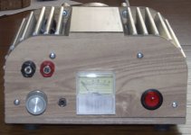
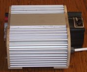
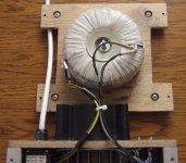
Here there are some photos of my Power Totem.
It is a mono amp: for a stereo system I will built another identical.
Attachments
Does it clip symetrically?
Why such a low efficiency?
Why only 10 watts classA when +/- 20v and 1.5 A bias?
Why such a high bias?
Is it not working in push-pull mode?
How bias is set?
Sorry for so many questions, but some explanations should be welcome.
The efficency with the SRPP (it doesn't matter if tubes or transistors) is only the 15% of the power dissipated. In any way, with a single ended operation system in real class A (symetrical clipping), it' s not fisically possible to overcome the 25% (15 Watts RMS in this case). The only way for to obtain this 25% is using the transformer in series to the collettor-drain-plate, but everyone knows how is critical and difficult to realize that device. You would have more efficency, but also more distortion coming from the transistor (collettor loaded) and from the windings and core of the transformer... What is good about this SRPP, is exactly its semplicity jointed with a particulary low open-loop distortion.
The clipping is symetrical and this is the reason why the bias is so high: in fact, the amp starts to clip the pick up and down at the same time only from 1,5 Apere quiescent current with a 8 Ohm load. If you would use a load of 4 Ohm, it would need a current of 2 Ampere for a symetrical clipping.... That bias is set by the values of the resistors R1 and R2: with higher values, lower currents and "vice versa".
The SRPP is an "asymetrical push-pull" circuit: the signal enter the lower Darlington that works as a common emitter with a voltage gain on the collettor loaded by the higher Darlington. The higher Darlington works as emitter-follower and gets the signal from the lower collettor in phase opposition with the input. So, the driveing signal of the higher Darlington is much more large than the one on the input of the lower Darlington (asymetrical push-pull). Because the higher Darlington is an emitter-follower, it doesn't gain nothing, so, the same amplitude of signal we will have on the lower collettor, we will have on the emitter of the higher transistor too. Shortly: the lower transistor gains voltage while the higher gains power an drives the load. It is a push pull, but does everything by it self...
Thank you for these nice explanations about this nice simple schematic.
This sight's angle adds to my understanding of the SRPP topology.
Wouldn't a 16 ohms load suit better in an efficiency point of view?
I am just an amateur, though, about class A efficiency,I read in the tubecad journal that a balanced SRPP can reach twice the bias current, such as a push pull. Reaching so ideally 50% efficiency.
In the real life , the Pass F5 ( i built some) for instance reaches 27watts average and dissipates 62watts... I may be wrong but i think Wen-San enhanced SRPP is quite that efficient.
Anyway, this Vetruvio's very nice schematic is worth to be experimented,in my opinion.
How it sound? I don't know if 1,5 % is a big percent of distortion or not, but I know that 10 Watts in pure single ended class A with a so simple circuit and with that quality of sound, I never found before... The amp sounds always sweet, even in the most complicated transients (scales of piano or female voices). Before I used a version of JLH for listening to the music at home (I loeved it)... Now I will use the "Power Totem"...
How the sound compare to the JLH '69?
Thank you for these nice explanations about this nice simple schematic.
This sight's angle adds to my understanding of the SRPP topology.
Wouldn't a 16 ohms load suit better in an efficiency point of view?
I am just an amateur, though, about class A efficiency,I read in the tubecad journal that a balanced SRPP can reach twice the bias current, such as a push pull. Reaching so ideally 50% efficiency.
In the real life , the Pass F5 ( i built some) for instance reaches 27watts average and dissipates 62watts... I may be wrong but i think Wen-San enhanced SRPP is quite that efficient.
Anyway, this Vetruvio's very nice schematic is worth to be experimented,in my opinion.
With a load of 16 Ohm the bias can be 1 Ampere, but the power is less because the load is higer. It's true that with 4 Ohm the quiscent current is 2 Ampere, but the output power increases to 15/16 Watts RMS...
I saw the schematic of F5 (great concept!), but it is not a single ended!!
Is a complementar push-pull of MOSFETs with a quiscent current for class A operation. Of course it can give 25 Watts. Practically it is a bridge of two single ended working in phase opposition by the complementar tecnology , but it could be biased as well as AB or B operation working the same perfectly. With the SRPP, JLH or Single-Output-Transistor, we are talking about that family of circuit that can linearly operate only in class A, called "single ended uotput stages". As well as mecanical engines: they can be 2 or 4 or 8 cilinders or simply Mono-cilinder (our case). If you are looking for efficency in this family of circuits, you are doing it in the wrong place. The goal or at least the tentative in this category is lower distortion, in particular about harmonic, switching, phase and intermodulation ones, not certainly the power.
I suppose Wen-San's project is better (I am not so expert), but certainly no more so simple.
Best wishes.
- Status
- This old topic is closed. If you want to reopen this topic, contact a moderator using the "Report Post" button.
- Home
- Amplifiers
- Pass Labs
- Excellent SRPP power amp of MOSFET