The idea is good for two stereo speakers, but not for a subwoofer. For a sub you need long horns plus the largest possible mouth area. Here would offer itself as a free mouth enlargement of the floor. This area would be given away (or not used) when set up in the middle of the room and on feet.
Therefore, I use the wall of the room as a mirror surface and also the floor, the ceiling and partly the Side walls. In theory I can get up to 22.5 m² horn mouth area. Theoretically...
Separating the subwoofer with just one coil is very sporty. In my listening experiments here with the incomplete horn was that with 10mH 0.7 ohm choke very unsatisfactory, but also understandable, because of Start an active separation at about 50-60 Hertz with Linkwitz 24dB / Oct. have provided.
If you plan a Sub, you have to x-over at very low freq.
D.W.
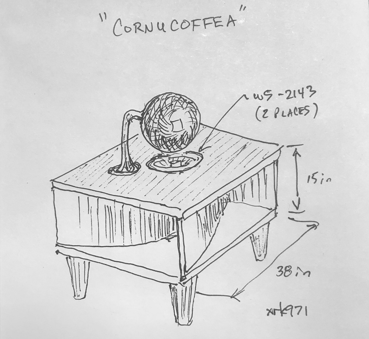
My plans have switched to a 1.5 way with the lower one going through first order coil below, say 600Hz. Of course, the W5-2143 can be used stood upright in the middle of the room as a bipole BLH and would actually work quite well as there is no baffle step due to it being a bipole design. The plans are being developed for this speaker and it may become a reality if I can find appropriate bendy plywood. I will CNC rabbet joints on both faces so that the bendy ply falls right in. Once glued together, should be a pretty sturdy structure given how much "bracing" it has from the 4 channels. I am going mono-omni for this speaker and letting an Amazon Dot (Alexa) mounted at the top of the sphere to provide the music streaming. All electronics including compact Class AB amp will fit inside the omni reflector sphere, so that only a power cord needs to go to the wall, otherwise play via WiFi and Bluetooth.
Last edited:
@ xrk871: Wait, I'm a bit confused ...
Are we talking about a subwoofer or two stereo speakers in your design?
To the lower chassis with the choke: I would then give the upper chassis a resistance equal to the RDC of the Throttle give, otherwise the upper driver (without throttle) gets more power than the lower and thus would be the Power balance disturbed. Or, better start building everything in "active" Design...
Yes, I also had the idea with the millings in the plates, but it was not possible here. For the sake of No one wanted to work with the heavy plates.
In this regard, I still have a valuable tip: use as much pressing force when gluing, as possible - I had also thought, here 8 threaded rods would reach in the middle ... Wrong thought, until now there are 24 threaded rods M8 and 8 pieces in M16 in it ..
Damn translating Machines...
Are we talking about a subwoofer or two stereo speakers in your design?
No more subwoofer - a full range "lounge" speaker to give my Alexa Dot some authority to play music. I was going to sum left and right with a pair of 4k7 resistors, then take the mono and drive two drivers in parallel as bipole. I could just leave the bottom firing one full range but afraid of all the mids and HF bouncing off the floor causing problems. So - lowpass the floor firing driver so that it is used for mid bass and bass. Probably will take a big fat inductor. Seems a bit of a waste of a full range to muffle its mids and highs with a coil. Perhaps some other 5.25in basic woofer could be used here in down firing position? Maybe a DC130B-8?
Dayton Audio DC130B-8 5-1/4" Classic Woofer Speaker
But 97dB at 50Hz for 2.83v will shake stuff in the house no doubt about it. Probably no more than 5w is ever needed here.
Last edited:
What do you guys think of me using bendy MDF for the channels instead of bendy plywood? It’s funny but this speaker may become a reality a lot sooner than I think. Zman01 was concerned about someone spilling coffee onto the delicate paper cone of the driver. After all it is a coffee table. It would collect and drain through the voice coil gap. What a mess that would be. Maybe a polycone sealed dust cap driver would be more appropriate?
Hi Cal,
Good to hear from you, you mean Tang Band, not Dayton... Let me see what the sims say. The bass hump will be well below 50Hz - that has to do with the length. The depth just needs to be adjusted to accommodate the Vas and Qts. Which are you leaning towards, the ceramic 8in or the 6.5in paper cone? Do you want one driver or dual drivers in bipole config like I have? The 8in will have to be scaled to 54in per side to fit the driver. Let's look at the more reasonably sized 6.5in. which is minimum 44in, so 48in is perfect.
X
Last edited:
Yes of course TB.
Old age is fun, you can forget things completely and then forget that you forgot, so you can forget all over again and never be the wiser.
OK, the 6.5" neo driver is a nice one and a lot lighter than the 8's. One driver per box. All I need now is some X magic to suggest the depth and when I have some time I will...
...well you know
Interesting and very doable - What about a cone with a flat top for the DOT to drop in. Might be easier than the sphere and go with the flat top of the table. Should give enough room for the electronics too. However, I have used a 6" plastic globe and place a DOT in the mouth (need to cut a little of the mouth.) It had room for Led colored lights but that might be too much. I later had to put a dimmer on them for a low romantic mood - thought that might get my wife in the mood - not happening.
XRK971 -
Inspired by your dipole coffee table idea, I am back to the idea of my smallish potable Cornu based music system. I was never able to get my head around the calculation software, but you seem to have one set up for cornus. Are you able to sim this design? Of course I can go bigger than 16x16, but this decreases the portability.
So, in essence, this post is to find out what is the smallest dipole Cornu which will play below ~70hz
The plates are 16"x16", and the two drivers (aucharm 4") take up ~4" so the volume of the "cube" is 16 x 16 x 4.
The mid-line of one "horn" is 55" long.
The grid on this plan is 1"
If this takes too much time, I will understand.
Colin
Attachments
XRK971 -
Inspired by your dipole coffee table idea, I am back to the idea of my smallish potable Cornu based music system. I was never able to get my head around the calculation software, but you seem to have one set up for cornus. Are you able to sim this design? Of course I can go bigger than 16x16, but this decreases the portability.
So, in essence, this post is to find out what is the smallest dipole Cornu which will play below ~70hz
The plates are 16"x16", and the two drivers (aucharm 4") take up ~4" so the volume of the "cube" is 16 x 16 x 4.
The mid-line of one "horn" is 55" long.
The grid on this plan is 1"
If this takes too much time, I will understand.
Colin
I can simplify this as a linear expansion for the inner section until it gets to the mouth area where it is closer to exponential. can you tell me the travel path from the throat driver chamber to where the expansion goes exponential and what the CSA is at start and at end? Then what is the length of the exponential and I will assume mouth ends at same as edge dimension.
70hz is tough - you need 1.22 meters path to do that. Is it that long?
And I think you meant bipole - that is what I am doing to reduce baffle step loss.
At the inner most part of one horn, the CSA is 0.5" x 4'. At the end is is 8' x 4". the distance between these points is 55" or 1.397 M.
The "exponential"-ness of this design is not purely scientific. It is an approximation to keep the build practical and the spacing of the waveguides semi - even. Looking at the plan I sent, does it look close enough to exponential? Toward the end, aesthetic concerns took over a bit so it would look even and still be "exponential". The original "exponential" curves did not look even or horn-like, but this could be my bias.
The "exponential"-ness of this design is not purely scientific. It is an approximation to keep the build practical and the spacing of the waveguides semi - even. Looking at the plan I sent, does it look close enough to exponential? Toward the end, aesthetic concerns took over a bit so it would look even and still be "exponential". The original "exponential" curves did not look even or horn-like, but this could be my bias.
Hi Cal,
Ok, let me take a hard look at the sim right now.
x
That W6-1139 has a powerful magnet, make the 48in Cornu only 4in deep. You need to make a bump out to allow the magnet to clear the back panel. Otherwise it has a huge bass spike overshoot at 35Hz.
Ok, let me take a hard look at the sim right now.
x
That W6-1139 has a powerful magnet, make the 48in Cornu only 4in deep. You need to make a bump out to allow the magnet to clear the back panel. Otherwise it has a huge bass spike overshoot at 35Hz.
Last edited:
- Home
- Loudspeakers
- Full Range
- Ever think of building a Cornu Spiral horn? Now you can!