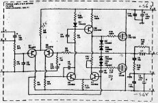
That is the Hitachi circuit and the Grandaddy of many popular designs, BJT and Mosfet.
I have a feeling it was also used in introduction of the the earlier Electronics Australia
magazine Mosfet Amplifier project and the ETI 5000 project article utilising the 477
modules. Silicon Chip used it to discuss their similar BJT topologies many moons ago too.
The dashed border line suggests it is from the ETI publication. Likely, it was also
published in international editions, though I don't know whether all ETI editions
reproduced it. If you look closely, you see the larger schematic connection points which were included on a complete amplifier.
Last edited:
Getting geared up to restore my old ETI Series 5000 power amp (which uses the ETI 477 boards )
Lots of learning from various forums with circuit modifications and updated components, so I thought "why not" !
I was not happy with the original boards, as some tracks lifted when I depopulated them and there was also some scorching around the BF469/470's
So, after a LOT of pain etc, I managed to copy the board design, created the Gerber file and had some (10) new boards made.
That's not exactly my experience but lets be clear, ETI 477 was just a single board amplifier PCB module intended for PA and general purpose use. A very similar design was adopted as part of the full Australian ETI 5000 stereo amplifier project designed by David Tilbrook (a member here incidentally) and the problems of stability in that application were addressed long ago - around 1982-84, IIRC.
ETI5000 was later refined as AEM6500 for another local magazine. This was a fully revised, developed and high quality design costing quite a lot more in parts. It has also been adapted to SMT in recent times by SuzyJ, here on this forum. Her professional board layout and mods were then pirated by a US company and sold there as a module on Ebay for some time and I'm sure she doesn't want that repeated so I doubt we will see more of her excellent work here.
The matter of dull sound is the same for all Mosfet designs because they need serious bias current before they sound any good and ETI designers and others who simply followed Hitachi's app note suggestions, all used a low 25 -50mA bias level, like a typical BJT design - duhhhh! That just isn't enough bias for low distortion but if 100mA is used (that's each output pair), the sound starts to improve a lot but the heatsinks required for 2 channels of 2 stereo pairs then become hot and expensive - that's the price of Mosfets.
The initial problems with stability were solved by just adding a couple of 100n greencaps (MKT) to the output stage as mentioned by george a but my build (ETI 5000) didn't require this. It's problems were in the signal switching design of the preamp. This was a very expensive DIY project with a complex and separate preamplifier that brought it to life when the parts sourcing and kit building problems were eliminated over some years. In all, you would need to have read articles and notes in several ETI magazine issues over a few years to get all the recommendations together and build it it right.
Maplin also used to have a kit that was not all that different in topology.
Mosfet Amplifier (EMM Jun 81)
Originally published in Electronics and Music Maker magazine
Mosfet Amplifier (EMM Jun 81)
Originally published in Electronics and Music Maker magazine
Hi Ian
George a here - (after all these years )
I noticed the eti 477 thread still going.
I think you covered the valid issues in your post.
To recap....my 477 was built on commercially bought pcb's
After the fire it was adjusted by way of the caps on the (source?) resistors so as to run without going nuts.
At that time I had no idea re the raising of bias to affect the sound ..I remember however using the recommended bias at that time..
It's funny that that when an amp bursts int flame that the memory lingers so long.
After reusing the mosfets to successfully "clone" the hafler - i had no interest in going back to the 477
YMMV
Actually I at that time had built the Haflers to replace a Phase Linear 400- which I had sold to incrementally fund various hifi pursuits
I was also uncomfortable with an amp that appeared to have a reputation to also burst into flames= not sure if the phase 400 deserved that reputation... but it did have a nice tight bass
Cheers from Oz
 Lenister Lad, a vendor thread has been created for you here: For sale ETI477 PCB's
Please read the rules regarding sales..
8: Posting overtly commercial information or advertising in non-commercial forums. (Note 4) Using the private messaging system or email to make unsolicited commercial advances is not allowed.
The matter of dull sound is the same for all Mosfet designs because they need serious bias current before they sound any good and ETI designers and others who simply followed Hitachi's app note suggestions, all used a low 25 -50mA bias level, like a typical BJT design - duhhhh! That just isn't enough bias for low distortion but if 100mA is used (that's each output pair), the sound starts to improve a lot but the heatsinks required for 2 channels of 2 stereo pairs then become hot and expensive - that's the price of Mosfets.
In my experience, the Hitachi/Renesas MOSFETs are positive temperature coefficient to around 50mA, so without some sort of bias compensation the bias won’t stay stable with low Iq settings. This probably accounts for a lot of the teeth gnashing around these devices. It can be fixed of course by simply treating them the same as bipolar devices in terms of bias setting, and the big (relatively to bipolar) crossover distortion at low Iq can be tamed by ensuring the rest of the amplifier has adequate bandwidth and gain to keep the output stages in line.
My AEM6000 derived amps (2 pairs of MOSFETs) make around 1ppm THD at 1KHz, 25W into 8Ω, and don’t run out of puff until well past 100W, so they’re competitive with, really, anything. see Suzy's Blog: Measuring a MOSFET Power Amplifier. Note that amp has no bias compensation, so I run it at 50mA per device.
The ETI477 doesn’t have any bias compensation, and the amplifier isn’t very fast, so unless you run them super-hot they don’t perform particularly well. Built with reasonable parts they are pretty hard to break though.
Last edited:
Hi guys and girls
I managed to acquire an original mint condition series 5000 (eti477) power amp. in remarkable condition. Was being used regularly and performing very well.
A quick look over before connecting speakers and noticed DC voltage on the speaker terminals. About 80mV on each (in the negative)
I ran my meter over the powered up circuit and all voltages measured pretty well spot on with the voltages noted on the schematic.
There were two different sorts of BC550 (different manufacturers) on each board, so I replaced all 3 on each board with new ones that I had and matched them to withing 2 hfe of each other ( hfe = 430 )
This brought the offset voltage down to about 50mV on each channel.
Ok but not great.
Warming Q1 up wit
h my finger sees the voltage drop down.
Warming Q2 up sees the voltage rise.
These two transistors are too far apart to thermally bond them for stability.
Is it possible that the BF's could be causing this ?
Any advice from the gurus here ?
It has also been adapted to SMT in recent times by SuzyJ, here on this forum. Her professional board layout and mods were then pirated by a US company and sold there as a module on Ebay for some time and I'm sure she doesn't want that repeated so I doubt we will see more of her excellent work here.
Meh. Why let one greedy twit ruin it for everyone. Here is a link to the thread with a newer version of the AEM6000 design, including gerbers.
- Status
- This old topic is closed. If you want to reopen this topic, contact a moderator using the "Report Post" button.
- Home
- Amplifiers
- Solid State
- Eti-477