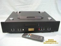
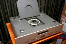
Who know the CD transport from attached images ?
Attachments
-
 ESTi ES-01AOOA-front-II.jpg41.2 KB · Views: 44
 -
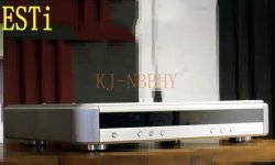
 ESTi ES-01AOOA-front-I.jpg62.1 KB · Views: 46
 -
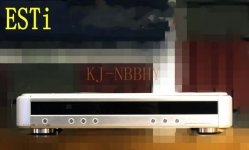
 ESTi ES-01AOOA-front-III.jpg40.1 KB · Views: 41
 -
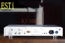
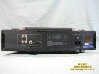 ESTi ES-01AOOA-rear.jpg45.2 KB · Views: 41
 -
 ESTi ES-01AOOA-side-view.jpg37.1 KB · Views: 42
 -
 ESTi ES-01AOOA-servo+display SAA7310GP.jpg61.3 KB · Views: 41
 -
 ESTi ES-01AOOA-servo+display PCB-II.jpg74.1 KB · Views: 41
 -
 ESTi ES-01AOOA-ZC93896P-II.jpg64.4 KB · Views: 36
 -
 ESTi ES-01AOOA-ZC93896P.jpg52.7 KB · Views: 39
 -
 ESTi ES-01AOOA-servo+display PCB-I.jpg65.4 KB · Views: 36
 -
 ESTi ES-01AOOA-servo+display PCB-IV.jpg69.9 KB · Views: 36
 -
 1517110836-2419467931_n.jpg34.4 KB · Views: 39
 -
 68d08729dc469834b917856ff86ce5bf.jpg28.2 KB · Views: 40
I saw one passing by years ago but I neither listened to it nor opened it.
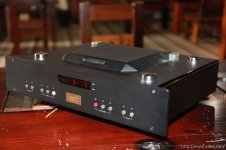
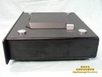
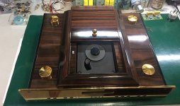
Seen from here it looks like a disgusting clone of the Philips/Marantz player, not very advanced and without an output stage in a homemade box.
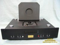
A strange thing is that the laser unit is mounted upside down (rotated 180°)
Seen from here it looks like a disgusting clone of the Philips/Marantz player, not very advanced and without an output stage in a homemade box.
A strange thing is that the laser unit is mounted upside down (rotated 180°)
This is a Taiwan product from moons agoWho know the CD transport from attached images ?
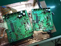
No, because I haven't this model on the desk.Looking quickly like this, it looks like a Philips CD 130/140 (cdm4/19) with a DIY PCB.
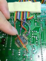
Can you have more detailed photos?
The image I upload in post #1 comes from a member from an other forum - I get it via PM.
He want to have more images so as a schematic diagram.
I know this kind of the PCB from an other English cd player from those days.
According the images of CD140 main PCB from Philips under
https://www-audiovintage-fr.transla...tr_sl=fr&_x_tr_tl=de&_x_tr_hl=de&_x_tr_pto=sc
I note no similarity concerning the kind of PCB.
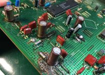
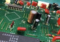
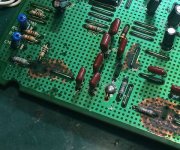
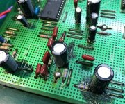
This Philips model use a usual kind, but the transport from ESTi use on their PCB instead a continuous copper surface (for the aim of screening) a grid-like structure.
I.e., no PCB for diy, evaluation and experiments, as to find in post #12+15 under
https://www.diyaudio.com/community/threads/vacuum-tube-prototyping-methods.390003/
a currently device of this brand - on aliexpress lo longer to find
Attachments
-
 H5914a852294244d089f50b228c69572ct.jpg_640x640q90.jpg38.2 KB · Views: 16
 -
 Hc467eb2d0e5f4b4b84f5541738cfbfc60.jpg_640x640q90.jpg39.3 KB · Views: 14
 -
 10866146_10152533398286962_7243275668565293669_o.jpg106.2 KB · Views: 15
 -
 H3ca0db05f69249f4a12d0c194085b0b6G.jpg_640x640Q90.jpg_.jpg30.8 KB · Views: 15
Last edited:
it looks like a Philips CD 130/140 (cdm4/19) with a DIY PCB.
I'm thinking of the basic structure of the diagram of a Philips reader transposed onto a custom PCB by ESTi.I note no similarity concerning the kind of PCB
What could be better and simpler to obtain a nice result and if you also put it in a pretty box, you get something very sellable and nice to put in a window.
- Home
- Source & Line
- Digital Source
- ESTi ES-01AOOA (CD Transport with CDM-4, Top-Loader like Krell MD-1/MD-10 or Vintage Micromega) SM and internal Images wanted