Coris, you have to remember, that when you're in Vendor Forums, the vendor has the moderation right. They do pay for being there.
Why don't you post your power supply problems over at TP own support forum. Someone might help you over there.
Sorry for polluting your threat.
Why don't you post your power supply problems over at TP own support forum. Someone might help you over there.
Sorry for polluting your threat.
Coris, I don't mind answering questions when posted with a good attitude, you just need to be much more respectful in your approach and tone. Part of that means not posting off topic. We have threads on placid. We also have a support forum.
First, neither of the power supplies you tested are stock. Second, the compensation scheme for both is designed with a capacitive load in mind. Try again with say47-100uf at the outputs. The reason for this is because of they are designed to work with our modules which will present such a load.
The non-HD placid is especially also *not* designed for the load you were testing it under. It was designed for < 250ma use. It can be used for more, but requires some component changes to do so.
A little respect and etiquette will take you a long way toward getting answers.
Cheers!
Russ
Last edited:
But anyway... I look forward to "hear" about your new experiments with different decoupling ways, caps types, and so on...
Me too.
Coris, I don't mind answering questions when posted with a good attitude, you just need to be much more respectful in your approach and tone. Part of that means not posting off topic. We have threads on placid. We also have a support forum.
First, neither of the power supplies you tested are stock. Second, the compensation scheme for both is designed with a capacitive load in mind. Try again with say47-100uf at the outputs. The reason for this is because of they are designed to work with our modules which will present such a load.
The non-HD placid is especially also *not* designed for the load you were testing it under. It was designed for < 250ma use. It can be used for more, but requires some component changes to do so.
A little respect and etiquette will take you a long way toward getting answers.
Cheers!
Russ
Sorry, but you can not talk to me about my missing respect to the TPA team, when you just delete quite systematic my posts. This is much unrespectful then my trying to get an explanation about a sold TPA product which did not function as expected.
You could very well answer to my post like you did here (except the "respect" chapter...), and maybe add that is not right place to post such subject on Buffalo 3 thread... Without just delete at once that post (as many before). There was many time before, many posts in the Buffalo thread which didn`t belonged exclusively to the Buffalo 3 theme. Nothing was deleted, but answered, explained.
I think you misunderstand what you name it "etiquette". As usually, are they who run a business, they who show first respectfulness for they who benefit of that run it business... This as a quite old principle world wide... No way to teach me about this.
I just had all the time a very good attitude, I trusted your way to do it in this field, and had full respect for your work. But unfortunately I have to experience your quite inappropriate way to accept the critic, or somebody else opinion.
I do not understand very well what you mean by "non stock" Placid. The assembled kits you have seen in my pictures was bought from TPA, and was assembled without any modification exactly as the kit provided. What do you actually mean "are non stock"? It is not TPA who made/sell this kit?
About the capacity on the PSU output (in the system/device) may be very clear précised about in the respective manual. When I came with the idea to use quite large decoupling capacities, so at least on the output of shunt regulators, you react immediately and almost called that a silly/stupid idea...
You have to know that I just assembled the Placid kits for use it to supply the Buffalo board. This problem I`ve came on with Placid oscillations was in direct connection with Buffalo use and not about any other experiments.
Sorry, but I had to tested Placid PSU before connected to Buffalo module... You may accept this procedure...
Last edited:
Coris, you have to remember, that when you're in Vendor Forums, the vendor has the moderation right. They do pay for being there.
Why don't you post your power supply problems over at TP own support forum. Someone might help you over there.
Sorry for polluting your threat.
Thanks for your explanation... I can well understand this. The only problem in this case is that the moderation have to be quite moderate... I`m not any concurrent who target to destroy that Vendor`s business...
Else, this problem with an bran new kit which oscillate after it is assembled is clear that is not only my problem... The information about one have to connect an important capacity on output or have this in the supplied device, have to be very clear précised.
The another Placid which I`ve claimed about in my posted post, had more than 20mV noise on output (with load) and more than 400mV without load... This could definitively not be my fault...
Last edited:
I do not understand very well what you mean by "non stock" Placid. The assembled kits you have seen in my pictures was bought from TPA, and was assembled without any modification exactly as the kit provided. What do you actually mean "are non stock"? It is not TPA who made/sell this kit?
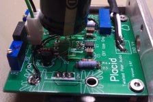
To me it looked like you have capacitance on both sides of the PCB. Definitely not stock.
I could be wrong. Though I did see that you have nice measurement gear.
This is very definitely not a stock placid.")
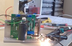
Yes, I can agree that this board do not looks very well now, like a new stock one. This do not mean that is modified the design on it or changed the components values. There was a space/place problem and few caps are replaced with the same value but ceramic type. This Placid do not oscillate, but have a quite big noise level on output (27mV-300mA load/400mV-no load).
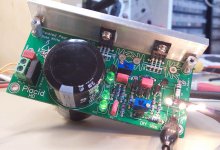
The another one is the big problem. Placid HD is very stock one. Build it as the kit provided. Only have a double filter capacitor on input (20000µ). This one have 5vpp/250Khz on output... With/without load. This is happen on low output current, and up to 400mA (set-up VR1), on 5,5v.
I will try to find out why...
Anyway the main aspect in all this was another one... The explanation, which I`ve asked in my (deleted) post, and can come out of this case can be maybe usefully for other members here... So I can hardly see the meaning with a very quick deleting of that post...
Attachments
Yes, I can agree that this board do not looks very well now, like a new stock one.
Yet you said it was...
I do not understand very well what you mean by "non stock" Placid. The assembled kits you have seen in my pictures was bought from TPA, and was assembled without any modification exactly as the kit provided. What do you actually mean "are non stock"? It is not TPA who made/sell this kit?
So what are we to make of this?
Your posts would have been welcomed in the correct forum or even in our vendor forum under the right thread.
Now I must say after your clear fabrication I am not sure you are welcome at all.
If you indeed have good will, you must more clearly demonstrate it.
Yet you said it was...
So what are we to make of this?
Your posts would have been welcomed in the correct forum or even in our vendor forum under the right thread.
Now I must say after your clear fabrication I am not sure you are welcome at all.
If you indeed have good will, you must more clearly demonstrate it.
Is not necessary to be so suspicious...
>Bunpei
Have you tried experiments with VDD as well as AVCC?
I recently tried to feed 1.2v VDD with salas shunt v1.1 although
v1.1 is said to be not suitable for such low output voltage.
(Anyway, my salas shunt reg sucsessfully outputs 1.18v to VDD and seems to be stable in my brief testing. I might try another version salas reg dedicated to lower out put voltages.)
This 1.2v VDD tweaking audibly helped to show some more details.
Still I'm not sure this improvement is because of whether changing regulator or not sharing pre-regulator stages.(I added another power transformer only for VDD)
Hi Bunpei
Tried today an 600µ ceramic capacity decoupling on VDD (with existing voltage regulator), inspired by wktk_smile.
For me is a big surprise... It seems that ES9018 work much better when have access to needed instantaneous current... It looks to me that a better solution for power this DAC is to have serial regulators with large decoupling on both analogue and digital...
or...
Even better: faster, lower impedance than any cap: shunt regs like Tridents or Hynes!
Hi Bunpei
Tried today an 600µ ceramic capacity decoupling on VDD (with existing voltage regulator), inspired by wktk_smile.
For me is a big surprise... It seems that ES9018 work much better when have access to needed instantaneous current... It looks to me that a better solution for power this DAC is to have serial regulators with large decoupling on both analogue and digital...
Even better: faster, lower impedance than any cap: shunt regs like Tridents or Hynes!
Barrows: Although marketing literature and forum posts may suggest otherwise, in reality it is not possible to ignore the effects of physical distance and circuit-board trace lengths on voltage regulator performance. An smd capacitor can be placed right on the load, meaning that there is practically no trace inductance or resistance to degrade whatever impedance curve the capacitor may have.
In contrast, a semiconductor regulator will be physically larger, and it will harder to place it physically close to the load. Even when the regulator has a superior output impedance curve in comparison to a capacitor, that impedance curve will be degraded by any trace inductance or resistance or lack of ground coupling that exists between itself and its load. This tends to be more apparent with shunt regulators than series regulators, due to the fact that shunt regulators consume more current and therefore run hotter than series types (meaning that bigger devices are required).
There is a difference between what a given circuit can deliver in the simulator and what it can deliver in real-life. Unless that is kept in mind, any conclusions will probably be suspect.
Also, there is nothing magical about the output impedance curve of a shunt regulator vs. series types. The output impedance curve of a shunt regulator can invariably be matched by using a series regulator. The reason should be obvious - in most cases a shunt regulator is nothing more than a series regulator that is turned upside down and fed from a high-impedance current source.
The real benefit of a shunt regulator is that it behaves as a real-time see-saw with the load, in a manner that makes the total current consumption constant. If the instantaneous current consumption of the load goes up, that of the shunt regulator will go down by the same amount. If the instantaneous current consumption of the load goes down, that of the shunt regulator will go up by an equivalent amount.
When shunt regulators are not employed, current fluctuations will travel upstream into the raw DC part of the power supply, and it will be possible for current spiking to appear on the grounds (particularly when the load exhibits any switching behavior, and this includes Class AB circuits). Neither of these are desirable conditions to have.
But this is a separate issue from the output impedance curve of the regulator.
hth, jonathan carr
Jonathan...
The DAC which is mentioned in this topic, has the option of using Trident shunt regulators which are quite small, and placed very, very close to the load: still, I am sure you are correct that even a few mm of pcb will have their effect, and a small smd ceramic may be of benefit.
No doubt that their are series regs which will exhibit the same low output impedance, but I was referring to the Trident shunts which are part of the design of this Buffalo DAC.
Thanks for your expert input.
Barrows: I have a Buffalo III with Tridents installed, so I am familiar with how close (or far, depending on whether you choose to be positive or negative about the situation - grin) they are to their respective loads.
What about the Paul Hynes regulators that you previously mentioned favorably? Are these small enough to be placed ascloseasthis to the load circuits on the Buffalo III?
cheers, jonathan carr
What about the Paul Hynes regulators that you previously mentioned favorably? Are these small enough to be placed ascloseasthis to the load circuits on the Buffalo III?
cheers, jonathan carr
Jonathan...
Very good explanation. I mean it in the same manner, and I should say the same, but you did it much better.
As I can see, there is a little confusion when one talk about ESS9018 DAC. This is automatic associated with Buffalo 2 or 3.
One should have in mind that ESS9018 is a chip, an DAC device and Buffalo is an product, an system which use that chip. Buffalo has some components in its system which work together in that way for bring out the result in the manner the producer has designed it.
There is no any standard or rule that ESS9018 have to use only Trident regulators to work in a DAC system and to give the most/best out of it in high fidelity sound results. Buffalo and its components is a way to use ESS9018. It is the most popular system for moment, because the performances and quite easy way to build it/use it. There are/can be very well another ways too in using this high end ESS9018 DAC chip, power it, firmware it, and so on.
The main meaning with this thread is to find and discuss another ways, all the possible ways to make it, to do it better, to have better results.
Let`s keep the mind open to what can be new and maybe better in all this...
Last edited:
I would like to point out something about low impedance on shunt regulators and when is to use quite large capacity as decoupling.
Let`s say we use an tantalum 47 - 100µ decoupling cap. A good one type can have as low as 0,02 ohm ESR. If is soldered right on the power pin is very possible that the chip will see almost the same impedance (0,02 ohm). If we solder 10 more another caps on that initial SMD cap, the chip will see something very near to 0,02/10 ohm. An 0,002ohm is a very low impedance (in this particular case). Right? Not to forget that a ceramic SMD caps it is supposed not to have at all ESR or parasitic impedance...
Maybe it is possible to rich the same figures with an shunt regulator. On the paper... But in real the regulator is much bigger then a small SMD cap. More than this, a regulator is build on a PCB, it is there traces between its components, and one can very hardly solder all that PCB right in the power pin of the chip. It could be a better way to solder all the components of that regulator together in between, without any PCB. But this is not practical if is about an sold product to someone else who will have to mount in the right place... The traces on the regulator PCB means in real impedance, which is hard to simulate in design process. Theoretically, one can have a very good figures about a shunt regulator impedance, but in real it could differ.
It is something else too. The traces between main PSU or even a more local PSU/regulator and the power pin of an chip have a physical resistance and impedance. If one place a quite large capacity on the end of that trace (on the chip), and have the respective capacity on the PSU output, then we can well have an pi filter there. This help enough in filtering process... And even the decoupling capacitor it self have very good filtering properties...
Last edited:
- Home
- Source & Line
- Digital Line Level
- ESS9018 - try new, try more...