Well, what about heaving an AVCC almost as from a battery?
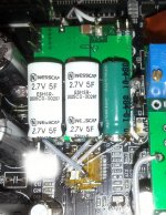
Because an 2,5F cap it can very well simulate a battery...
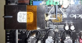
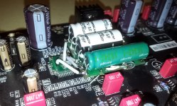
I have found a smaller dimensioned double layer cap, but 6 times higher capacity than the previous cap I used. Its ESR is higher than another one cap: 0,08ohm. but I think this detail is not so important here...
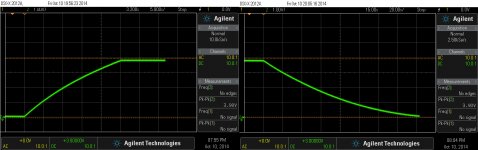
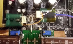
It is the same regulator, which it charge this huge capacity, in 25s, as you may see in the pictures here. By the way, the regulator it is a LT1763, but it have a transistor on its output...
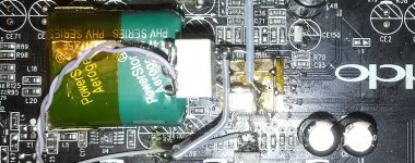
I chosen to add a discharge device for this cap, as at its capacity, it may take teens of minutes to be completely discharged. So a relay connect a load to the cap terminals at the power off. The discharge time is to be seen in the picture here.
I think I will stop here with increasing the filtering capacity for AVCC. Further increasing of this capacity it may not bring much more improvements for the audio outputted, and the charge/discharge time it goes over a reasonable level.
But what about the sound out of a such configuration? The obvious (perceptual) improvement is in the lower end of spectre (of course...). It increase a lot the precision of the bass sound elements in the sound scene, with a very much increasing of the dynamics in low end spectre. Such low frequency sound components are very well defined in space, and can be easily located. The improved reproduction of harmonics in the low spectre, and the plentiful of these it complete in a very special way the another sound elements in the rest of the audio spectre. It bring like more colours nuances and gradients to the sounds... It improve a lot the fidelity of reproduced sounds, it give to it weight and power (for the same decibels of course).
I think it may be a clue to improve in this way all the ES9018 power rails, but to manage so many such high capacities at power up/down it may be a challenge...
Because an 2,5F cap it can very well simulate a battery...
I have found a smaller dimensioned double layer cap, but 6 times higher capacity than the previous cap I used. Its ESR is higher than another one cap: 0,08ohm. but I think this detail is not so important here...
It is the same regulator, which it charge this huge capacity, in 25s, as you may see in the pictures here. By the way, the regulator it is a LT1763, but it have a transistor on its output...
I chosen to add a discharge device for this cap, as at its capacity, it may take teens of minutes to be completely discharged. So a relay connect a load to the cap terminals at the power off. The discharge time is to be seen in the picture here.
I think I will stop here with increasing the filtering capacity for AVCC. Further increasing of this capacity it may not bring much more improvements for the audio outputted, and the charge/discharge time it goes over a reasonable level.
But what about the sound out of a such configuration? The obvious (perceptual) improvement is in the lower end of spectre (of course...). It increase a lot the precision of the bass sound elements in the sound scene, with a very much increasing of the dynamics in low end spectre. Such low frequency sound components are very well defined in space, and can be easily located. The improved reproduction of harmonics in the low spectre, and the plentiful of these it complete in a very special way the another sound elements in the rest of the audio spectre. It bring like more colours nuances and gradients to the sounds... It improve a lot the fidelity of reproduced sounds, it give to it weight and power (for the same decibels of course).
I think it may be a clue to improve in this way all the ES9018 power rails, but to manage so many such high capacities at power up/down it may be a challenge...
Attachments
BTW, the discharge time of the AVCC cap is defined by the a approx 100mA discharge current. I could increase this current to have a faster discharge rate, but then it may have impact over the small relays contacts, or I should use a bigger relay... Well, maybe I will improve this part of the project in the future. It seems to work well so far, as it is...
Recently, in addition to these AVCC cap experiments, I have (for the first time for me...) connected together the ES9018 outputs in 4+4 configuration (stereo). So, the outputs dacB and dac from one side of the chip, for a stereo channel, and on another side accordingly, for the second stereo channel.
I have used the chip`s datasheet as guide in this task. Quite surprised to experience that the right stereo channel was completely silent after all was done, even though I could see the HF DAC characteristic noise on both both stereo channels. But the audio signal was present on output, only from left stereo channel.
I found out finally that the DAC outputs DAC2/DAC2B, it have to be connected in opposite position than the datasheet shows. Switching in between these DAC outputs, connected together to the rest outputs on right chip`s side, everything was working well.
Is this a known (issue)? I`m a little bit confused about if it have to be like this...If is so, then it may be something wrong with the datasheet of ES9018... It may be something wrong with my DAC chip (production fault)?
I was supposing that the Right/Left sides of the chip, as shown in its datasheet, it have to be symmetrical when about outputs designation...
Many thanks for eventual clarifications/confirmations from someone else...
OK. The datasheet is right, I checked the output polarities.
The outputs can be inverted in software. It is possible that the Oppo guys swapped polarities to simplify their layout. Your fancy Agilent scope should be able to sniff the I2C bus and catch a write to Register 13 : DAC Polarity...
About your Tower Of Capacitors :
It is a well known fact (and my measurements confirm it) that AVCC supply is critical for ES9018. Especially in Voltage mode... does it work in Voltage mode or current mode on your board ?
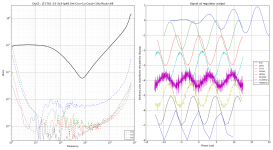
Anyway, see attachment, this is LT1761 regulator's output impedance... I don't get why audiophiles seem to fall in love with it, it is by far the most expensive of the bunch and doesn't show particularly interesting performance. For the test it had a BYP cap, I don't remember the value. This is what causes the drop in output impedance (good), and its rise at LF (bad).
Perhaps the fact that it has a rising output impedance at LF explains why when you add more caps to compensate, it sounds better !.....
The outputs can be inverted in software. It is possible that the Oppo guys swapped polarities to simplify their layout. Your fancy Agilent scope should be able to sniff the I2C bus and catch a write to Register 13 : DAC Polarity...
About your Tower Of Capacitors :
It is a well known fact (and my measurements confirm it) that AVCC supply is critical for ES9018. Especially in Voltage mode... does it work in Voltage mode or current mode on your board ?
Anyway, see attachment, this is LT1761 regulator's output impedance... I don't get why audiophiles seem to fall in love with it, it is by far the most expensive of the bunch and doesn't show particularly interesting performance. For the test it had a BYP cap, I don't remember the value. This is what causes the drop in output impedance (good), and its rise at LF (bad).
Perhaps the fact that it has a rising output impedance at LF explains why when you add more caps to compensate, it sounds better !.....
Attachments
Right, right! That`s it! They swapped the channels for layout reasons... Good to know about this...")
Thanks peufeu for your comments.
I have the board working in voltage mode. Well, I agree about LT1761/63. Is not my choice about this regulator, but the Oppo designers (for costs reasons), as I use their device for my experimenting, tests, and so on... I did not changed the original configuration used in Oppo players about AVCC stage. In HA-1 they use TPS regulators. Much better...
Thanks again for your help/contributions...
It is definitely the large decoupling capacities with increase quite dramatic the analogue/sonic performances of the ES9018 DAC chip.
..
This is consistant with many circuits and thier PSU...
THxRNMarsh
This is consistant with many circuits and thier PSU...
THxRNMarsh
Yes, is right, of course...
After using a very large capacity on AVCC, and getting the improvements described above, I thought it is not quite right to ignore the another power rail for the analogue stage (core - VDD L/R) of ES9018...
Well, I have used the same capacity (2,5F) for 1,2v VDD L/R of the chip, while keeping the existing (not just high quality) regulator.
The result is just impressive. Especially for the soundstage quality. The even more increasing in precision for the sound elements in space is just unbelievable (at least for me...). The dynamic is increasing so, that become quite obvious that the band, orchestra, or whatever is just in the room. The very low spectre sounds are extremely well defined as location. No any sound is coming from everywhere, but from a very precise location, as it was recorded. Such precision for low end spectre sounds is fully remarkable. It only miss from these "scene" to see the musicians, instrumentalists, vocalists... The sound and the dynamics of the soundscene are just as experienced in front of a life event. All this at relative low volume...
To experiment with these very large decoupling capacities, I have disconnected (lift it up) the analogue stage power pins from initial layout. A grounded shield was placed in between the chip and the new power connections. There is of course an experimental configuration... Which it works amazing!
Attachments
Last edited:
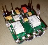
This is the final version of my AVCC/VddL/R PSU.
It use 2x5F (serial connected) caps for AVCC, with a total ESR of 60mOhm, and 3F cap of 80mOhm for VDD L/R.
1,2v VDD is delivered by a LDLN015 regulator. For AVCC it is used the ADM7151 as adjustable regulator. Both tensions come up to the normal level quite simultaneous in approx. 15s.
The both rails are independent with separate grounds. These grounds are to be connected together at the common GND point (ES9018 ground pins). Of course, the shortest possible connections with the DAC chip is a must.
I have tested it so far for 80mA load, and the chips temperature do not exceed 35dg.C. The relays it discharge the caps at power off. Resettable fuses protect and cut the currents, in case of any failure in discharging circuits.
Two such modules it can power the ES9018 for all rails.
Attachments
Last edited:
Tested the Sabre PSU together with the DAC chip... Full success!
The sound quality out of the DAC system is dramatically improved. Especially the low end spectre is reproduced with a unbelievable definition, dynamic, deepness.
I have to notice once again that the ESS9018 is just an exceptional DAC, which it can give a lot if it get what it need...
My PSU board design is already improved (the adjustment potmeter it can be mounted now on opposite side too), and its dimension a little bit smaller.
Attachments
Last edited:
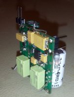
There may be an option to use resistors to discharge the caps. But I think is not just the right option in this case.
I use the very simple, old, and good bulbs (as the pictures reveal), which are more suitable for this function. The miniature bulbs may fit to the discharge currents. A more advantage to use bulbs is also the visual indication of the process.
A resistor for discharging circuits it should be quite high power rated to sustain the discharging currents. It may be a big component. The resistor it show a constant resistivity to the cap, the discharge process it happen in a linear way, and it may be longer. A old classic bulb it function in a different way, and it lower its internal resistivity as it get cooler.
Have Edison ever dreamed that its invention it may be very actual, and useful in a high tech world?
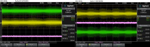
A slightly lower HF noise at the DAC chip output, when using this PSU.
There is here about balanced outputs, measured in similar conditions, before and after connecting this large capacities PSU.
Please notice that in my post DAC processing are not involved filters.
There is here about balanced outputs, measured in similar conditions, before and after connecting this large capacities PSU.
Please notice that in my post DAC processing are not involved filters.
Attachments
When I tried before 3-4 years or more?
ES9008 24bit version I put on Avcc Voltage reference circuit around AD797 for each channel, and it was awesome really...
On the other OLD but good 14bit TDA1540 (simply could not resist to build...) I put higher values for end caps close to the chip - I can confirm similar effects on sound...
btw good old ceramic chip is piece of work really
After successful experiments, tests and daily use of the very large capacities PSU (analogue rails) for ES9018 (presented here previously), I intend to extend these experiments for the two digital rails of the DAC chip.
While the very slow power up sequence for AVCC and VddL/R, do not represent at all any issue for the functionality of ES9018, I`m not very sure about the impact of a so slow power up rate for the digital power rails of the chip. As I can see, there is no any request in the ES9018 data sheet for a well defined power up sequence, either for analogue or digital power pins.
Any opinion, thoughts about?
When DVCC is down, if the main processor or clock oscillator sends signals (I2S, clock, etc) to the DAC, a current will flow from the digital inputs, through the internal diodes, to DVCC.
This can have various effects, depending on the chip and the current, it can do nothing, just burn the ESD protection diodes, or trigger latch-up and self-destruct. YMMV. I would advise against it though...
This can have various effects, depending on the chip and the current, it can do nothing, just burn the ESD protection diodes, or trigger latch-up and self-destruct. YMMV. I would advise against it though...
Thanks peufeu for confirming my concerns about this approach...
I think it will be only for the analogue power rails of ES9018, which it will benefit of this special way of powering it. At least in my vision...
Here is the implementation of my PSU (final version)...
I think it will be only for the analogue power rails of ES9018, which it will benefit of this special way of powering it. At least in my vision...
Here is the implementation of my PSU (final version)...
Attachments
Last edited:
- Home
- Source & Line
- Digital Line Level
- ESS9018 - try new, try more...