I bought an Espey model 200 AM/FM radio years ago in an antique store. It has two 6BE6 pentagrid tubes, two 6BA6 pentodes and a triode near the tuning capacitor. The sound is excellent compared to other tubed FM radios I've tried. It had two 6V6 tubes in push-pull for the sound output, which I modified to use with two old 7591 pentodes. I read that tuners with pentagrid mixers have lower distortion compared to using a pentode mixer. The radio seems to be well aligned, too. Its originally mono and I modified it to connect to a stereo demodulator (RCA phono jack on the back connected to the ratio detector according to an article I have). I tried connecting it to an amplifier (7591's removed and ratio detector output going directly to the amplifier) and it has good dynamics and low distortion (better than a Dynaco FM-3, for example). I was thinking of modifying the FM-3 so I can connect the Espey 200 to it and use the FM-3 stereo demodulator to get stereo.
I found a schematic for an Espey 511 which looks similar. I was planning on tracing out part of the circuitry for the 200 to see if the tuner part is the same as the 511.
http://t000bs.topcities.com/schematics/Espey511.htm
I found a schematic for an Espey 511 which looks similar. I was planning on tracing out part of the circuitry for the 200 to see if the tuner part is the same as the 511.
http://t000bs.topcities.com/schematics/Espey511.htm
Tom Bavis said:200 is in Sams folder 247-4 - I'll see if I have it.
I'd like to have a copy of the schematic for a 200, if you don't mind.
I found some interesting patents on frequency conversion with pentagrid and other multi-grid tubes.
US 2616033 Converter
http://v3.espacenet.com/origdoc?DB=EPODOC&IDX=US2616033&F=0&QPN=US2616033
column 1, lines 5-28
In the reception of radio waves incorporating signal information modulated on a high frequency carrier, it is customary to heterodyn the incoming signal with locally generated oscillations in order to provide an intermediate frequency signal which is readily amplifiable before detection. When the carrier frequency is very high, the second or even a higher order harmonic of the local oscillator voltage is often used to mix with the incoming signal thereby to provide a signal at a desired intermediate frequency. The use of such harmonic conversion permits greater local oscillator stability than is obtainable with fundamental operation, due to the lower operating frequency of the local osillator. When employing second harmonic conversion, it is desirable to suppress to as great an extent as possible any intermodulation products of the incoming signal and the fundamental frequency of the local oscillator. It is an important object of the present invention, therefore, to provide an improved converter which utilizes second harmonic conversion and in which intermodulation, products of fundamental conversion are substantially rejected.
6BE6 and references
US 2637808 Oscillator for am-fm receivers
http://v3.espacenet.com/origdoc?DB=EPODOC&IDX=US2637808&F=0&QPN=US2637808
US 2516272 Frequency conversion system
http://v3.espacenet.com/origdoc?DB=EPODOC&IDX=US2516272&F=0&QPN=US2516272
7Q7 4 grid converter, separate LO and LO frequency multiplier
pentode RF amp
Not to be a wet blanket, but bear in mind that this radio may not have sufficient IF bandwidth for good (or any) stereo performance.. You need a reasonable linear phase response over a bandwidth of 300kHz for good FM stereo. (Not to truncate the sidebands.) Most mono receivers are deliberately designed with less IF bandwidth than this, it helps selectivity amongst other things.
Also I am not convinced that a pentagrid converter confers any advantage over a triode based or pentode based mixer stage, mixing is an inherently non-linear process and mixer harmonics should be well outside of the pass band of the IF in any case. My understanding is the pentagrid converter was nothing more than a way to reduce the tube count for economy, and incidentally I have not seen this approach used for FM only AM - not to say that this isn't an exception. (And I haven't had a chance to read the patents you provided yet due to time constraints - I'm at work on a quick break. So I could be wrong.)
There may be other factors not touched on here accounting for the good sound quality you get from this set.
I found some links to Sams Photofacts with Espey 200 schematics here:
http://www.olditemsale.com/espey.htm
http://www.smcelectronics.com/sams.htm
Looks like they have it at the Library of Congress.
http://catalog.loc.gov/cgi-bin/Pweb...ALL&PID=9610&SEQ=20060316180016&CNT=25&HIST=1
I could just trace out the ciruit in the tuner to see if its the same as the 511.
------------------------------------
More info on pentagrid mixers.
http://www.analog-rf.com/mixer.shtml
http://www.olditemsale.com/espey.htm
http://www.smcelectronics.com/sams.htm
Looks like they have it at the Library of Congress.
http://catalog.loc.gov/cgi-bin/Pweb...ALL&PID=9610&SEQ=20060316180016&CNT=25&HIST=1
I could just trace out the ciruit in the tuner to see if its the same as the 511.
------------------------------------
More info on pentagrid mixers.
As the number of stations increased and the power levels also increased; receiver performance had to improve. The pentagrid converter, such as the 6BE6 tube (British EK90 valve), was introduced which was optimized for mixer performance. This included the isolation of local oscillator and input signal as well as allowing the first grid and cathode to work in an oscillator configuration. These tubes allowed a closer approximation to the multiplication of the two sine waves which produced fewer spurious mixing products.The British used a 7 grid tube with similar multiplication properties in FM broadcast receiver demodulators. They picked signals off the primary and secondary of the last IF double tuned transformer (which were 90 degrees out of phase) and multiplied them.
http://www.analog-rf.com/mixer.shtml
In this case they are referring to the demodulator stage at the end of the IF and not the mixer. The technique is referred to as phase quadrature demodulation and several variants of this circuit technique were widely employed on cheap tube B&W tv receivers in the U.S. during the 1960's, this mainly for economy. (It had really lousy incidental AM rejection - AKA the buzz heard on scenes with a lot of white in them.) Different application than a mixer down converting to IF.
The problem with tube quadrature detectors is they depend on the quadrature (coil) phase relationship being very precisely tweaked to provide the 90 degree phase shift required for proper demodulation, tiny shifts in tuning due to temp/time/misalignment result in really poor AM rejection and linearity issues as well. Actually based on specs I have read/experienced the quadrature detector's linearity at higher deviations wasn't all that good compared to either the ratio detector or foster-seeley.
6BE6 was commonly used in AM broadcast receivers and its advantage was that the mixer and oscillator were combined saving tubes and parts. The comments in the 6BE6 blurb are standard marketing clap trap, no high performance general coverage receiver ever used these tubes, and in fact you will find them most commonly employed in the AA5 (All American 5) where cheap ruled the day. Good RF performance requires both gain and selectivity ahead of the mixer (i.e. r.f. amplifier) and an oscillator that is not pulled by varying loading in the mixer at different frequencies which is just one of the reasons why separate oscillator tubes and buffers were often used in good shortwave GC receivers. For the best practice in AM/SSB receiver design take a look at any of the Collins stuff. IMO the 6BE6 would be very useful as the mixer/oscillator for the 2nd IF of a dual conversion receiver where it operates at a fixed frequency. (With xtal control.)
IMHO the Foster-Seeley discriminator with a couple of limiters is the best performing discrete FM detector with the ratio detector being next best at a considerable reduction in cost and complexity. (Limiters not needed, although sometimes used to improve AM rejection further.) Quadrature detectors while interesting imo seem to perform less well in discrete implementations, but are extremely common in IC based receiver ICs.
I am not saying that the Espey is not good sounding or even that it is not necessarily suitable for your intentions, just to be aware of the potential pitfalls.
Most of these techniques were clever developments driven by the need to reduce cost in tv and radio receivers of the time, and are not necessarily driven by pure performance considerations, although the descriptions in patent submissions may make those claims.
IMHO The Dyna FM-3 is a very good sounding tuner in its own right, you might be well advised to update it and do a realignment.
Good luck..
As you can see from the schematic.
http://t000bs.topcities.com/schematics/Espey511.htm
The FM section uses a pentagrid mixer, a separate local oscillator and a pentode RF amp. They didn't do this to save on tubes.
http://t000bs.topcities.com/schematics/Espey511.htm
The FM section uses a pentagrid mixer, a separate local oscillator and a pentode RF amp. They didn't do this to save on tubes.
6BE8 AM Tuners
Hi Kevin,
I am very interested in your comments on the 6BE6. I am just getting back into tube equipment and have two dysfunctional receivers which both use this tube in their AM section.
Each has a 2 position switch for AM sensitivity.
The Sansui 1000A has this lineup: 6BA6-6BE6-6AQ8-6AQ8
The Kenwood KW-60 has this lineup:6BA6-6BE6-6BA6-OA81(?)
What is your opinion of these arrangements? Would either tuner
have a potential problem in an urban area with a lot of AM stations?
Thanks, Victoria
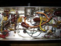
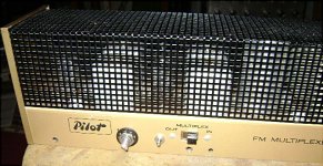
I connected my Espey 200 to a Pilot 100 demodulator and am getting good results from them.
Espey 200 am/fm radio & Pilot 100 stereo demodulator
Espey 200 am/fm radio & Pilot 100 stereo demodulator
Pentagrid mixers are not a good idea at VHF because they are too noisy. This means you need a high gain pentode as an RF amp, but you still end up with more noise and inferior signal handling. Better to use a triode or pentode mixer, with cascode or grounded grid RF stage.
I have several Pilot T-601 FM tuners that use the 6BE6 as a complete converter (no separate LO tube). This tuner came out in 1946, one of the first to tune the modern 88-108MHz FM band. I find that only one out of four NOS 6BE6 tubes will oscillate properly at these frequencies. Most will either take off at UHF, or die out half way up the band. I suspect that Pilot either sourced specially spec'd 6BE6s, or cherry picked them in the plant. But, with the right tube, this little tuner is stable and sounds quit nice.
Bobby Dipole
But, with the right tube, this little tuner is stable and sounds quit nice.Bobby Dipole
You can download information about the Pilot T-601 here: www.pilotuner.com
It has a 6BA6 RF amp and 6BE6 mixer/LO. The Espey 200 has a separate LO.
One's for sale on Ebay
Pilotuner FM radio pilot tuner vintage tube with manual - eBay (item 130465389808 end time Dec-19-10 19:07:34 PST)
It has a 6BA6 RF amp and 6BE6 mixer/LO. The Espey 200 has a separate LO.
One's for sale on Ebay
Pilotuner FM radio pilot tuner vintage tube with manual - eBay (item 130465389808 end time Dec-19-10 19:07:34 PST)
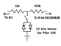
19 kHz limiter for stereo demodulator
I got the idea of putting a 19 kHz limiter in my Pilot 100 stereo demodulator from these three patents.
US 3235663 Fm stereo multiplex receiver having limiting means in the pilot channel
US 3287501 Multiplex detector circuit
clipper 35
US 3270138 F. M. stereophonic receiver having noise prevention means in the pilot circuit
The simplest modification seemed to be to use antiparallel diodes across the signal path to clip positive and negative peaks outside the +/- 0.6 volt range (for two silicon diodes). I put the limiter at point A in the schematic http://members.shaw.ca/pacifictv5/pilot100.jpg .
The limiter includes a 10k resistor between tank circuit A1 and the 470k resistor with the antiparallel diodes connected between ground and the connection point between the 10k and 470k resistors. I put a switch in the circuit to switch the diodes in and out of the circuit to compare the effect with and without the limiter. WMUC (88.1 MHz) broadcasts with 10 watts of power and when the Pilot 100 is set to stereo, usually a grumbling splatter sound can be heard during silent passages which seems to be from interference from nearby stations, like NPR on 88.5 MHz and probably other stations. Sometimes when WMUC is off the air I can hear a lot of noise at 88.1 MHz which sounds like other stations bleeding over into that frequency, as well as another distant station on 88.1 MHz. Switching the diodes into the circuit essentially causes the grumbling splatter sound to disappear, but some noise can still be heard at a lower level during silent passages. Its a distinct improvement. Before this, I put a 500k pot having a switch in the Pilot 100 between the slide switch stereo outputs as a blend control which can be switched on and off and adjusted between stereo and mono. Blending the left and right outputs tends to reduce noise since the stereo noise is out of phase in both channels.
------------------------------------------
Here's some other examples I found which use antiparallel diodes for limiting signals.
US 3250919 Amplitude limiter using tunnel diodes
US 3448359 SELF-ADJUSTING COMPENSATOR PREFERABLY FOR MEASURING RECORDERS
antiparallel diodes 32 (fig. 2)
US 3102991 Sonar equipment for single-transducer operation
US 4357690 Switch circuit for exciting ultrasonic transducer elements
Popular Electronics Magazine
scroll down to and click link to the M/M/M Instrument Amplifier
Google Patents
http://antiquesci.50webs.com/Espey200.htm
Attachments
Last edited:
If you scroll down on this page about the Dyna FM-3, you can find a link to the manual.
http://sites.google.com/site/mpbarney/dynacofm3
On the 5th page of the manual under "The Multiplex Inegrator" it says the triode half of the 6BL8 doubles the 19 kHz signal and also acts as a limiter, holding a constant 38 kHz level to reduce noise and preserve stereo separation. There doesn't seem to be a 38 kHz oscillator in the Dyna FM-3. It generates the 38 kHz signal from the 19 kHz signal after the FM signal is demodulated.
I put a dynamic limiter in the Espey receiver with amazing results, ie. lower noise and better stereo separation. Details are at the bottom of this page.
http://antiquesci.50webs.com/Espey200.htm
http://antiquesci.50webs.com/Espey200.htm
- Status
- This old topic is closed. If you want to reopen this topic, contact a moderator using the "Report Post" button.
- Home
- Amplifiers
- Tubes / Valves
- Espey AM/FM radio (pentagrid mixer, etc.)