This was already suggested by AndrewT in post 55, at the end. I believe base stopper are always a good idea, EF or CFP.Hi kalmara,
If you have not solved oscilation problem yet, try to insert 100 ohm resistors to Q5 and Q6 bases. CFP is prone to oscilation and you included CM and with it more gain.
dado
I also would like to see if kalmara could solve, and in case the updated schematics. Long time ago I also was doing something like that ....
")
bye
effebi
Phase lead capacitor
Sorry to ressurect this old thread. I built a P3A and I'd like to take the most out of it. I was wondering about the phase lead capacitor - the cap between VAS colector and LTP feedback base. I don't have a scope. What would be the optimum value for this cap? Is there any way to calculate it?
Thanks.
Nope. Remember that output stage distortion tends to dominate, and that increasing Cdom reduces open-loop GBW - so there's less open-loop gain to suppress output stage distortion. But obviously low distortion is of no use if the thing oscillates like mad in real life.
Given the flexibility in power devices, it is to be assumed that the default value of C4 is chosen to be on the safe side. If you don't have a scope (or even an RF probe), it is best left at the standard 100 pF.
Given the flexibility in power devices, it is to be assumed that the default value of C4 is chosen to be on the safe side. If you don't have a scope (or even an RF probe), it is best left at the standard 100 pF.
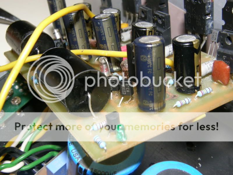
Power supply caps on the Rod P3A Rev B board
sorry to resurrect an old thread.
I am now populating the boards and notice that there is a long distance between the 100uF power suppply caps and the 100nF bypass caps.I would like to seek answers to these
1) Is there any advantages in using 480 Uf caps?
2) Can i solder the bypass caps on the underside of the power supply caps ?
3) In the place of the bypass caps , i am thinking of placing 47 Uf caps that i have lying around. Can i use higher value and is there any trade off ?
4) Is the value of the bypass caps critical? which is better --l ceramic bypass caps or mkp caps ?
thanks
kp93300
Hi, the schematic of P3A is very similar with P101...is it posible to modify the P3A with the input from P101?....what value Ra and Rb should have?....thanks
60-80W Power Amplifier
Project 101 - High Power, High Fidelity Lateral MOSFET power amplifier
60-80W Power Amplifier
Project 101 - High Power, High Fidelity Lateral MOSFET power amplifier
Attachments
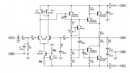
Rb has the same voltage as Vbe of Q11.
In that location Rb defines the current out of the tail of the LTP.
Ra feeds Q11 so that Q11 can operate as an amplifier.
Q1 & Q2 could work as inputs (there are two inputs) with as little as 100uA and as much as 10mA. you choose a value that gets good performance of the transistor AND gets adequate amplification of signal to feed into the second stage.
Q11 ca work within a similar range of current for it's Ic.
But look at the quiescent power of these devices and at the peak power.
- Status
- This old topic is closed. If you want to reopen this topic, contact a moderator using the "Report Post" button.
- Home
- Amplifiers
- Solid State
- ESP P3A Mods/Upgrades