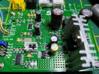
Hello! I am new to this forum. Sorry for my English, I am writing through a translator. Recently, I became the owner of the ES9038 board and the Amanero Interface. For a start, I did bipolar power + -15 on the LM317 / LM337. But I did not like the fact that the LM317 is very hot. This is because on the +15 line there is a display and power to the chip. In addition, the linear stabilizer at 5v on the board was very hot. I felt sorry for the capacitors on the board and I decided to make a separate stabilizer + 5v. And on my transformer there is a winding for 10v. After assembling the stabilizer, the board became cold and I really like it. And separated supply is better, I think. I also added 2 3300uf capacitors to the AVCC, as advised to beginners. The operational amplifier was first OP275, then the original LME49720MA came to me. But I had one problem that made me worry. The op amp is hot (50+ degrees when measured with a thermocouple). The old OP275 or NE5532 was a bit warm. Can this self-excitation? Or so it should be with these amplifiers?
Ps. I read and translated the forum for a very long time, looked at how other people are refining this board, and I also want to do this in the future. Markw4, you do amazing things with your boards! This long journey that you have overcome is worthy of respect!
What I want to do next: I wanted to use superregulators to power AVCC, clock, and so on. But people began to abandon them. As I understand it, at the moment the best solution is the LTC6655 reference voltage chip and an operational amplifier at its output. And I want to repeat it too. Or is it better to first cleanse the supply + -15 and +5?
Hi pixel28,
First, I would agree with you that it is better to use a separate, external 5v supply instead of using the original 5v linear regulator on the dac board. The original regulator does tend to get hot and waste power.
As it turns out, power supply quality is very important, IMHO, to make a good sounding dac. The ES9038Q2M probably performs best with separate voltage regulators for DVCC, VCCA, AVCC_L, AVCC_R, and the clock module (although the clock can be on the same power as VCCA, according to ESS, haven't tried that way myself though). In particular, the two AVCC supplies are very critical to get right. ESS recommended an old, well-known opamp supply in a paper available on their downloads page: http://www.esstech.com/files/4514/4095/4306/Application_Note_Component_Selection_and_PCB_Layout.pdf
There is some other info of possible interest there as well: ESS Technology :: Downloads
Although ESS used filtered 3.3v as the reference for the opamp AVCC supplies, it turned out that better subjective sound quality was found to be improved experimentally using a precision low-noise reference LTC6655.
Schematics for AVCC and an output stage as drawn up by MrSlim can be found attached at post #3003 of this thread. Instructions for building a through hole component output stage can be found at: Dropbox - Output Stage Instructions.zip ...although I would probably prefer an SMD solution as being easier and possibly better.
For the 3.3v power supplies, I used LTC1763 regulators for Clock, VCCA, and DVCC. Those regulators are soldered to the bottom side of the board's ground plane. The 5v supply provides input power for all the 3.3v regulators and the power for the LTC6655.
If your output opamp is getting hot, it could be that some RF from the dac or from the digital end of the board is getting into the opamp somehow. Checking with a scope would probably be the best thing to do.
If you decide to build a better output stage, then there are at least a couple of ways to approach good sound quality with respect to the effects to of the +-15v opamp power (used for the output stage, and for the AVCC dual opamp). Either a very fast, high feedback power supply can be used, perhaps such as the Twisted Pear Placid HD, Jung regulators, or nazar regulators. Otherwise, the way of doing it is to use a more traditional power +-15v supplies such as perhaps a two stage LM317/LM337 power supply (two sets of +- regulators in series) with maybe somewhere between 15uf and 110uf of high quality film caps from each of the +-15v rails to ground. That really makes the opamps sound nice and as they should sound. I used the film cap approach myself, but it can be rather costly (but so can some of the other options). The lowest cost approach, one that I have not tested myself, but our member eziitis recommends is a nazar power supply. Depending on the approach that one wishes to try, it may be helpful to start planning from an early stage, since output stage bypass caps might be different depending on what one wishes to try.
EDIT: A clock upgrade can help sound quality too. A better filter cap as recommended by ESS for DVDD is also advisable.
Last edited:
Thank you for such a detailed answer, Mark. The Nazar regulator is very interesting to me. Perfect performance for ridiculous money! I found a lot of Nazar supply schemes, but it's hard for me to figure out which one would be perfect for me. They are designed for different loads in general, on two, three or more transistors. I think this will be a very good mod for the output part of my project. Apparently I will have to consult with a member of Eziitis. But first I need to solve the problem of heating the op amp.
Regarding the heating of the operational amplifier, I have a very cheap analog oscilloscope, which will not show anything bad) I will try one of these days to contact a friend who has a good oscilloscope. But I do not know how to measure it, where to put the probe (At the output of the amplifier at minimum volume, as I understand it?)
Regarding the heating of the operational amplifier, I have a very cheap analog oscilloscope, which will not show anything bad) I will try one of these days to contact a friend who has a good oscilloscope. But I do not know how to measure it, where to put the probe (At the output of the amplifier at minimum volume, as I understand it?)
Mark, why did you stop on the LTC1763 regulators? Because there are many other LDOs with less noise at frequencies of 10hz - 100khz and high PSRR (LDLN015, LP38798, NCV8570 for example). For my experiments at a local store, I found a very cheap analogue of the LTC1763, although with a bit more noise (24 µVRMS) - IFX1763XEJV33XUMA for only ~ 0.4 $ per piece. I think to start building the Power Clock, VCCA, and DVCC using 3 pieces on the back of the board.
Mark, why did you stop on the LTC1763 regulators?
Just what I happened to have. I can tell you the dac performs very well.
Also, one of the more popular series of voltage regulators for high performance digital and sometimes analog are made by Torex: https://www.torexsemi.com/file/xc6219/XC6219.pdf ...in some cases if they are used for more critical applications, pi input and output filters may be used before and or after the Torex regulators.
Next dac I would probably try some other regulators. ADM7150 is used by some high quality dac makers for AVCC and for all the 3.3v stuff. Some use ADM7154. I would not conclude by looking at a data sheet alone what will work best for high performance audio. Some measurements and listening tests may be appropriate too.
Sometimes it is output impedance over a certain range of frequencies that matters more that noise or PSRR. It just depends.
Unfortunately, there may be some tendency for data sheets to emphasize what the manufacturer wants you to know, not necessarily everything you might need to know for your application. Its up to you to make sure you are not getting fooled into using something that is not best for your app. I think a lot of people found out that the Chinese LT304x regulators built according to the data sheet recommended layout did not work well for Sabre dac AVCC. Everyone who switched to an opamp supply (or maybe an ADM7150 supply for the PRO dacs that need more current) found how much better that sounds than LT304x. Easy to hear the difference, everyone seems to say. The most impressive noise specs available did not seem to be what was needed most for that particular application.
EDIT: If eziitis doesn't say anything about nazar regulators before too long, I will see I can look up the notes I kept from when he talked about it before.
Last edited:
Regarding the heating of the operational amplifier...
I would probably look at the output and the power rails.
You might try putting something like a 2,000pf X7R ceramic cap directly across dac outputs for each channel and before they go into the opamp.
You might also try putting the dac board inside a steel case, which can be good for shielding out external RF (just in case there is any issue with that). LME49720 and other opamps in that same family can be rather sensitive to RF at a couple of GHz, although distortion is usually more the symptom rather than heating. I have seen some heating from our dac boards before (not only me), and there was some low level RF at the opamp output. It was substantially improved by adding small-ish feedback capacitance.
Ultimately, once I got the +-15v power supply working well enough, I switched to OPA1612 opamps, which seem at least somewhat less sensitive to RF. I also found when I laid out the new 'through hole' component output stage, that heating was no longer an issue at all with it. One thing I did was twist together wires for the two outputs for each dac channel and run the twisted pair along the dac board ground plane. Perhaps, between the common mode and differential mode capacitance, it was enough to sufficiently attenuate whatever RF was coming out of the dac.
Last edited:
Link to eziitis' post on nazar regulators: https://www.diyaudio.com/forums/digital-line-level/314935-es9038q2m-board-386.html#post5698160 ...It is post #3851 in this thread.
In case anyone following our thread here is interested, there is someone with an AD1955 DAC evaluation board, including the USB interface who is looking to give it away for free to someone who will use it. Unfortunately for some possibly interested folks shipping is limited to US addresses only, a stipulation of the person wanting to find a good home for the board. I checked, and it turns out Digikey has one of the evaluation boards in stock: https://www.digikey.com/products/en?mpart=EVAL-AD1955EBZ&v=505
Some further info on the dac chip and the board:
https://www.analog.com/media/en/technical-documentation/data-sheets/AD1955.pdf
https://www.analog.com/media/en/technical-documentation/user-guides/UG-048.pdf
https://www.analog.com/media/en/technical-documentation/application-notes/AN-1006.pdf
Again, the primary interest is just to give the board to someone who will actually put it to some good use, rather than stick it in a drawer or something like that.
I should probably also mention that some eval boards I have gotten from TI and LT did not have software available that could work with any OS later than maybe WindowsXP. Might be the same issue with this board, don't know. With the boards I got, I had to read the data sheets and write my own Arduino code to program them, something there was no easy way to find out until I got the boards here and tried to use them (this happened with every one of the 3 various types of eval boards I have purchased). So, I would suggest that anyone interested in the eval board might want to keep that possibility in mind, and be prepared to deal with whatever may turn out to be necessary in order to use the dac board.
Last edited:
Hello to all.
I want to share my impressions. A new es9038q2m board came to me, 3 tps7a4700 units of regulators, two boards of voltage regulators, one - kubota with bipolar power and the second - a board with lm317. There are two power supplies. Both are bipolar. One used to power the analog part from kubota. The second is to power the AVCC, clock and the rest through lm317.
Impressions. Best powered with a separate transformer winding for AVCC. For everyone your ldo. Also, improving AVCC’s power supply alone doesn’t give such a good effect as compared to when to improve the power supply for the rest of the DACs and clocks. For this, too, used ldo. Compared with what was before the fashion - this is a tangible result!)
The hump on the sound mentioned above and which recognized the ESS decreases with improved nutrition. According to my feelings. Also using solid-state capacitors for 270 microfarads after ldo tps7a4700 did not see any improvement - in my opinion it only got worse. Something happened at the same time with the middle frequencies. High steel "thin". Did not like in general. I use with the control panel from apple.
Plans to change the clock on the Crystek CCHD-957 100 MHz. But something the Chinese began to offer only 950 ... (Markw4, how do you look at the "950"?
Regarding Kubota - poorly stabilizes nutrition. It "floats" at 0.2-0.3 v. For the operational amplifier will go. It is worth opa627. I want to output sound through audio transformers. A friend is a fan of tube sound. (He himself once had a tube amplifier.) He also advised to bring sound through a transformer. And also strongly recommends changing the clock to a good one. And then put the tube preamp. I agree with him. Since the es9038 chip itself is bright - the lamp would be in place. In any case, there will be an listening experience in this version.
The system I have so far is this - a computer - a hub - an amplifier mx50-se + mod - speakers 4 * 40W noname (not really bad according to the frequency response). There was a bipolar power preamp on opa2604, there is no such thing on aliexpress, there is tao. It is necessary to refine it - no desire. Direct from the DAC to the amplifier is better.
There is no photo of all my work - everything is still collected in boxes from under power supplies from computers.
Markw4 THANK YOU VERY MUCH !!!!!
Hi 888777,
Don't think Crystek makes CCHD-957 clocks for 100MHz, they are only for lower frequencies. Therefore, we usually use CCHD-575 for 100MHz. Probably a little better than CCHD-950 for that.
Regarding ES9038 tendency towards brightness, yes, there is some of that, but it sounds much more balanced in tone when the implementation is good enough. I would suggest to do everything you can to make the dac sound good and of balanced tone first before thinking about trying transformers and tubes. That means besides good power supplies for everything including all dac chip voltages, clock, AVCC and output stage power, you would also need a good clock upgrade, and a good output stage. In addition, you need to get into the dac registers and get DPLL down as low as possible, and also use harmonic distortion compensation. Once it sounds as good as you can get it would be the time to think about adding transformers and tubes. Its because those last two things, transformers and tubes shouldn't be there as band-aids to try to cover up whatever is wrong with the dac. That never works right. Just turns bright and distorted into more distorted muffled mud, or maybe into more distorted crisp mud. Either way it isn't good. If the dac sounds good and you have good transformers and good hi-fi tube circuitry, it can be okay. But, it will be more distorted for sure. You can get much of the same effects by slightly detuning the harmonic distortion compensation. More 3rd harmonic to simulate transformers and probably more 2nd harmonic for tubes. However, once you hear the dac with optimized harmonic distortion compensation, you might decide it doesn't actually sound better when you start turning some of the distortion back up above the minimum. You could at least try it before adding transformers and tubes, maybe save some money that way.
Last edited:
"In addition, you need to get into the dac registers and get DPLL down as low as possible, and also use harmonic distortion compensation." - I do not understand how to do it.
1. Good. Watch buy CCHD-575 100MHz.
2. I will take into account your advice not to rush to the lamp.
3. I already have 2 opa 1612. Tell me a scheme?
4. What then to do with Kubota - tension floats on it. For a good output stage, this is not very good. Although at this stage without alterations completely come down.
Hi Mark,
After replacing the 7805 which wasn't the problem I moved on to the capacitors which all checked out within tolerance and low ESR.
I started on a continuity check across the board, comparing the two boards, the one that runs cool and this one that gets too hot to touch, on checking this point on the board (with the cap removed) I get continuity on the 'hot' board whilst there is no continuity on the other.
This might be the cause of most of my problems!
Attachments
Last edited:
This might be the cause of most of my problems!
Hi damiangt3,
Interesting. That is the output filter cap for the 3.3v regulator. Is the dac still working with that cap removed?
"In addition, you need to get into the dac registers and get DPLL down as low as possible, and also use harmonic distortion compensation." - I do not understand how to do it.
How one would go about doing it depends on the dac one is starting with. ES9038 dacs generally have an MCU that controls the dac chip over I2C bus. The data sheet for the dac chip describes what the I2C bus registers do. Usually, the hardest part is getting physical control of the I2C bus away from the board's MCU. After that it is simply a matter of programming an Arduino, or some other MCU of one's choice to program the dac chip registers as desired.
Hi damiangt3,
Interesting. That is the output filter cap for the 3.3v regulator. Is the dac still working with that cap removed?
Oddly enough, yes.
Right now I'm thinking is it really worth trying to find out where the problem is or just order a replacement! It won't stop me fiddling away whilst it's on my desk, 2x magnifier in hand and my multimeter nearby!
Oddly enough, yes.
Right now I'm thinking is it really worth trying to find out where the problem...
Probably good to have a cap there, although for ES9038Q2M to sound its best eventually the whole 3.3v regulator situation along with all the loads now connected to it would have to be addressed. For my modded dacs, the original 3.3v regulator now only provides power to the MCU chip.
Probably good to have a cap there, although for ES9038Q2M to sound its best eventually the whole 3.3v regulator situation along with all the loads now connected to it would have to be addressed. For my modded dacs, the original 3.3v regulator now only provides power to the MCU chip.
I've got a couple of superregs arriving soon to supplement the onboard 3.3s and then I'll do some work on the I/V stuff, at that point I'll probably call it a day with this board.
Just what I happened to have. I can tell you the dac performs very well.
Also, one of the more popular series of voltage regulators for high performance digital and sometimes analog are made by Torex: https://www.torexsemi.com/file/xc6219/XC6219.pdf ...in some cases if they are used for more critical applications, pi input and output filters may be used before and or after the Torex regulators.
Next dac I would probably try some other regulators. ADM7150 is used by some high quality dac makers for AVCC and for all the 3.3v stuff. Some use ADM7154. I would not conclude by looking at a data sheet alone what will work best for high performance audio. Some measurements and listening tests may be appropriate too.
Sometimes it is output impedance over a certain range of frequencies that matters more that noise or PSRR. It just depends.
Unfortunately, there may be some tendency for data sheets to emphasize what the manufacturer wants you to know, not necessarily everything you might need to know for your application. Its up to you to make sure you are not getting fooled into using something that is not best for your app. I think a lot of people found out that the Chinese LT304x regulators built according to the data sheet recommended layout did not work well for Sabre dac AVCC. Everyone who switched to an opamp supply (or maybe an ADM7150 supply for the PRO dacs that need more current) found how much better that sounds than LT304x. Easy to hear the difference, everyone seems to say. The most impressive noise specs available did not seem to be what was needed most for that particular application.
EDIT: If eziitis doesn't say anything about nazar regulators before too long, I will see I can look up the notes I kept from when he talked about it before.
Yes, the ADM7150 (or all the same ADM7154?) Is really a very good option. Now I wonder how many parts to divide the power of the DAC itself (VCAA, DVCC, Clock). For watches, a separate regulator is desirable, as I understand it. In the future, it will still have to be replaced by Crystek and it will be good for him. As for the VCAA, DVCC lines, I don’t know whether it is necessary to divide them. I looked at your photos # 3006, as you did the power and I had questions about the inductances on the board. Should I use them with new regulators? For watches you do not use them, although for VCAA (one point is directly connected, and the other, which is located near DVCC, goes through inductance). An interesting decision, but why did you do so?
In the output part, I stopped at the Nazar regulator, I will do it in the near future.
An interesting decision, but why did you do so?
So far as I know, the inductors were probably included to help prevent HF/RF noise produced by the various 3.3v loads from getting back into the original 3.3v bus. With a separate regulator for each load, not so clear if the inductors are still serving a useful purpose. So far, I haven't noticed an audible advantage connecting power before or after the inductors. Where the power wires are attached now is where I last happened to leave them, that's all.
Regarding VCCA and DVCC, I think the reason ESS brought out separate power pins for them, and the reason they use separate regulators on evaluation boards for DVCC and VCCA+Clock is to help keep deterministic noise produced by one load from introducing unhelpful noise/interference into the other load(s). I would recommend to use separate regulators if one is going for good performance, and maybe use a shared regulator only if low-cost and simplicity are more important considerations for the particular dac project.
Last edited:
- Home
- Source & Line
- Digital Line Level
- ES9038Q2M Board