Hi friends,
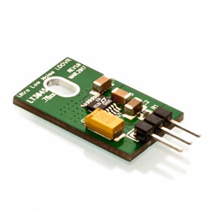
I'm thinking of buying this ES9038Q2M Board (v1.06) and connect it directly to my Pi3 via I2S ( not via USB Amanero). I just wonder if this connection (directly from Pi3 to ES9038Q2M) can play DSD native or Dop ? Has anyone try before and give me some review?
Thank you so much !
Hi.
You cand play DOP but not native dsd as far as I know.
My 1.04 board is connected to rpi3+kali using 2is.
I do not see why it should not work. If you have a heap of LT3045s at hand, set one as pre-regulator for 5V and second as post-regulator for 3.3V. It's a bit overkill and I am not sure if the SQ will be better as if you leave the 7805 in place, but it should work. Keep in mind the board has other flaws that will limit achievable SQ, though...
Ok thank you.
I will order a LT3045 is 3.3v and give it a try.
voodoo3: as far as I know there is stil no driver available for direct I2S connection of RPI to this board :-(. I hope someone will prove me wrong...
I use audiophonics 9028 driver for Moode audio


I will try to replace AMS1117 with LT3045-78xx Ultralow-noise (0.8µVrms) 3.3v.
But I'm very new to all these mods and I don't know how to solder the 3 pins of the LT3045 and the ams1117 seems to have 4 legs.
May some of you help me if he knows how to do it?
Thank you

But I'm very new to all these mods and I don't know how to solder the 3 pins of the LT3045 and the ams1117 seems to have 4 legs.
May some of you help me if he knows how to do it?
Thank you
Attachments

Last edited:
Sorry but with almost no knowledge of electronics, i don*t recommend to modify that board. And i don*t see that anybody did serious modifications on that board.
For better result i will use another output stage. And do independent supplys with lt3045... 42. I think LT are perfect for supply sharp sounding ES dac.
For better result i will use another output stage. And do independent supplys with lt3045... 42. I think LT are perfect for supply sharp sounding ES dac.
Hi.
You cand play DOP but not native dsd as far as I know.
My 1.04 board is connected to rpi3+kali using 2is.
Thank you @terry22 and @MBA
Sorry but with almost no knowledge of electronics, i don*t recommend to modify that board. And i don*t see that anybody did serious modifications on that board.
For better result i will use another output stage. And do independent supplys with lt3045... 42. I think LT are perfect for supply sharp sounding ES dac.
It's only a desoldering/soldering job, no?
But I understand your point of view.
I will try to replace AMS1117 with LT3045-78xx Ultralow-noise (0.8µVrms) 3.3v.
But I'm very new to all these mods and I don't know how to solder the 3 pins of the LT3045 and the ams1117 seems to have 4 legs.
May some of you help me if he knows how to do it?
Thank you
I've ordered the same device, with the same idea in mind. Unfortunately, I am out of the country for 2 more months, before I can look at what needs to be done. Has anyone done any schematic reverse engineering from this board yet?
Despite of the fact that to do some mods you sould have some knowledge, I will try to help.I don't know how to solder the 3 pins of the LT3045 and the ams1117 seems to have 4 legs.
May some of you help me if he knows how to do it?
Thank you
Indeed, AMS1117 have 3 pins - see datasheet. Namely, tab is the same connection as pin 2 (VOut). And at our board VOut trace is connected to tab (not to pin 2). Pinout of AMS1117 is:
1. Ground
2 and Tab - VOut
3. VIn
As I remember, in your small PCB with LT3045 pinout is the same as L7805 (for example, see datasheet too), i.e.
1. VIn
2. Ground
3. VOut
So, you need:
- desolder AMS1117
- place your PCB with LT3045 on original board somewhere near the L7805 (or 7808, it depends on version of original DAC)
- solder pin 1 of that PCB to pin 3 of L7805 in case of ver 1.06 (or L7808 in ver. 1.04)
- solder pin 2 of that PCB somewhere to ground (I think the simplest way is to do it via the existing hole to bottom layer)
- solder pin 3 of that PCB to the trace where tab of AMS1117 has been soldered
That's all. See also my picture in the post #336 for your reference (in that case pin 1 of my patch PCB is VOut, pin 8 is VIn, pins 3,6,7 is ground).
Easy current mode
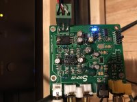
I wanted to see if I could put this board in current mode with little changes. Managed to do so.
Steps
1. Shorted all the 6.3k resistances (made it 0 ohm). This offers a virtual ground to the negative pin
2. Added a 2.4K in parallel to the 8.3K feedback resistor. This corrects the dc offset on output and gives a 2V RMS output
3. Added a 100uf cap from the + leg of the balanced output to ground. This provides a virtual ground to the positive pin of the DAC. It also provides reference voltage to the opamp +ve input
So effectively a unbalanced current mode.
For those who like the relaxed tonally correct current mode - this is the easiest
Still. I prefer the transformer coupled output in voltage mode

Hi Terry
I can try to do a step by step but the some instructions will be for you to try and experiment
1. Choose a transformer. My experience has been that a 1:4 transformer is ideal because one can push a Sabre DAC closer to the current mode by loading it with 1/4 the DAC impedance and still get a 2V RMS.
2. Amorphous cores are neutral and clear and resolve detail much better than mu-metal cores but mu-metals add a warmth and paint the scene with a thicker brush - primarily due to hysteresis - they add a second order harmonic. It is your call depending on the rest of the system. I let my preamp add second harmonics rather than depend on the transformer for the warmth. Sometimes that speakers themselves have high order second harmonics because of the unequal tensioning of the m-roll and spider. I have found that this in-phase second harmonic causes more reflected sound in open baffles that I prefer. In sealed cabinets - it creates less resonance and back EMF. In ported - more bass.
3. Load the Sabre DAC with an resistance equal to the DAC impedance or lesser. The lower you go - less the distortion and the output (closer to true current mode) but the dynamics (or slam) suffers. I find that loading the DAC with a resistor that is slightly less the output impedance of the DAC is better.
4. The loading resistor can be grounded at the center (so a 390 ohm resistor can be 195+195 in series with the middle point grounded).
5. A capacitor is essential across the legs or from the mid point of divided resistance bridge. I have found that a capacitor across the legs sounds better when cornered at 20K-22K (3 db corner). The quality of cap also matters. I preferred Silver Mica. You can try other caps. So for ES9018 - I have a 47nf shunt across the primary creating a 3db corner at 20K
Hope this helps
PS> I happened to read Ian detailed thread about transformers and posted a reply to his thread here - http://www.diyaudio.com/forums/pc-b...i2s-dac-hats-raspberry-pi-15.html#post5369493
His diagrams and the thread itself may help you more than my long description.
I can try to do a step by step but the some instructions will be for you to try and experiment
1. Choose a transformer. My experience has been that a 1:4 transformer is ideal because one can push a Sabre DAC closer to the current mode by loading it with 1/4 the DAC impedance and still get a 2V RMS.
2. Amorphous cores are neutral and clear and resolve detail much better than mu-metal cores but mu-metals add a warmth and paint the scene with a thicker brush - primarily due to hysteresis - they add a second order harmonic. It is your call depending on the rest of the system. I let my preamp add second harmonics rather than depend on the transformer for the warmth. Sometimes that speakers themselves have high order second harmonics because of the unequal tensioning of the m-roll and spider. I have found that this in-phase second harmonic causes more reflected sound in open baffles that I prefer. In sealed cabinets - it creates less resonance and back EMF. In ported - more bass.
3. Load the Sabre DAC with an resistance equal to the DAC impedance or lesser. The lower you go - less the distortion and the output (closer to true current mode) but the dynamics (or slam) suffers. I find that loading the DAC with a resistor that is slightly less the output impedance of the DAC is better.
- For ES9018 (4 channels paralleled into one) - I use 390 ohm leg to leg so 195 per phase. ES9018 is 195 ohms per phase/leg. Then taking into account the secondary impedance reflected back from the preamp - it actually results in a 303 ohm impedance presented to the DAC. With a 1:4 - I get more than 2V RMS (nearly 3V RMS actually) but I can digitally lower the volume to 2V RMS. Big advantage with boards that have higher THD+N at 0dbfs.
- For this board (ES9038Q2M) and ES9018K2M - the output impedance of the DAC is nearly 750 ohm (approximated - it is actually 744 ohm for ES9038Q2M and I think 774 ohms for ES9018K2M). So the loaded + reflected impedance should be nearly 650 ohms.
4. The loading resistor can be grounded at the center (so a 390 ohm resistor can be 195+195 in series with the middle point grounded).
5. A capacitor is essential across the legs or from the mid point of divided resistance bridge. I have found that a capacitor across the legs sounds better when cornered at 20K-22K (3 db corner). The quality of cap also matters. I preferred Silver Mica. You can try other caps. So for ES9018 - I have a 47nf shunt across the primary creating a 3db corner at 20K
Hope this helps
PS> I happened to read Ian detailed thread about transformers and posted a reply to his thread here - http://www.diyaudio.com/forums/pc-b...i2s-dac-hats-raspberry-pi-15.html#post5369493
His diagrams and the thread itself may help you more than my long description.
Not the best solder job. I just wanted to do this last test before I got back to transformers
Hi,
this is my first post.
I have the board version 1.06, can i do the same mod??
Is the position of the capacitors right?
Please, see the immage.
Can I use the same resistance value (2.4K) to stabilize the RMS?
Thank you
Attachments
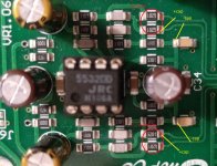
Yes. You can.
You will need to desolder the output caps and short them if you want to avoid them. One leg of the resistor can be soldered there. I used 2.7K actually and have some DC offset. I think 2.4K should work to null it. I initially soldered a 780 ohm resistor thinking the output impedance of the DAC was 780 ohm per leg but then it had 1.5V DC offset at the output and the output was also nowhere near 2V RMS (much lower instead). If I have time tonight - I ll tell you the exact value to have a OV out. I just didn't bother because all that the offset did was make my pot scratchy in my preamp. I didn't care much for current mode although it was better in some ways (lower THD) that the original circuit.
Yes.. your pic looks right. Make sure you short the SMD points after you desolder the resistances
- Home
- Source & Line
- Digital Line Level
- ES9038Q2M Board