Hi Freezebox,
Opamps are cooler, but hard to say why. They are are not SMD so their cases are larger to dissipate more heat for one example.
Regarding output stage filtering, too soon to say. Have to finish every last mod to know for sure how much difference it makes. Very hard to remember back to several months ago when the first dac was modded this far and compare on that basis.
Mark,
I haven't read this entire thread yet, so may have missed it. I have the exact same version of the Smpcb controller that you are using. I've tested Toslink and that works fine. I've never messed with I2S, but would like to get it to work as well.
I believe I properly matched the Pi pins to the Smpcb I2S inputs correctly. What is the next step? I'm just experimenting at the moment. No need for customization yet.Do I need to get Linux loaded and a Volumio to test?
Thx,
Hi redjr,
Are you saying you have one of the green dac boards and you want to connect it to RPi using I2S?
If so, there are three signals and a ground that would need to connected up. They are, (1) DATA - aka serial data or PCM data, (2) BCLK - bit rate clock, (3) LRCK - left/right clock or sample rate clock, and (4) GND - ground.
There are three different formats for sending PCM data, they are (1) left justified, (2) I2S - aka Philips I2S, and (3) right justified. The first two are very similar, just a small difference in where LRCK changes state.
Sometimes the term I2S is used as shorthand for any or all of the three PCM types and or the type of serial audio bus using the signals defined above. By default Saber dacs expect I2S, although they can be configured for left or right justified.
For most of the dac boards we use, the first two jumpers, J1 and J2, should be on to select I2S. Both jumpers off may work too.
By the way, in case you already knew all of the foregoing stuff, thought I would mention it for anyone wanting to know more. Sometimes we have readers with similar questions or who are curious to learn more about these things when the subject comes up. (Please come up with that list for me, Alex
)Once the hardware is hooked then RPi software would have to be configured to send data. Not an expert on that, but think there are some in other parts of the diyaudio forum. Or, maybe someone who knows more about that will chime in here. If you have to go looking for someone, you might try here: https://www.diyaudio.com/forums/pc-based/
EDIT: I do at least know you need some version of Linux, perhaps Volumio or one of the other versions or environments tailored to streaming audio seem most common and probably gives best performance and features.
Last edited:
Hi Mark,
Thanks for your reply and explanation of the various forms of I2S. I learned something!
Electrically, I had everything connected properly.(It's playing now!). I'm a new user of Roon and was unaware that RoPieee has a configuration setting for selecting a Pi using I2S. Once I selected that option rebooted RoPieee she started singing like a bird. I'm glad I finally got around to playing with I2S output on the Pi. Before it's all been DAC hats - many of which are Plug-n-Play. This opens up a whole new realm of using DACs and the Pi. Great knowledge for my projects ahead.
Thanks again.
Last edited:
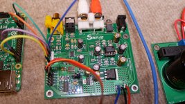
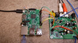
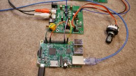
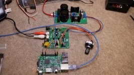
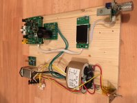
Here are a few pics of my setup on the bench.
Very nice, and thank you for sharing. We like to see what setups look like.
However, if it is okay to say so, I see many opportunities to improve sound quality, if that might be something of interest. Some very noticeable improvement might just come from adding another $32 or so board to the setup. Namely, one of these: AK4137 I2S/DSD Sample Rate Conversion Board Support DOP input digital lcd | eBay
for I2S only, or one of these if SPDIF and TOSLINK were wanted too:
HIFI AK4137 DAC SRC flagship high-end audio 786K 32Bit DSD256 DSD IIS conversion | eBay
It also occurs to me that RPi can also be used as an I2C master, which could be used to control the ES9038Q2M chip control registers. You could get a quick reduction in distortion there too since your dac appears to still be running in voltage output mode. If you can figure out which pins to use for I2C we could talk about how to make good use of it.
Note: for those who may not already know, I2C is a two wire plus ground fairly low speed control bus that is used to for lots of things including for configuring many, many different kinds of complex integrated circuits. There is a data signal wire, SDA, and a clock signal wire, SCL. I2C - Wikipedia
Last edited:
Thanks for those great suggestions. At the moment, what you see is just my prototype. Once I decide on how I'm going to implement this project, proper enclosure, layout, display options and proper cabling decisions will be made. This setup was simply to prove to myself I could get it all to work!Very nice, and thank you for sharing. We like to see what setups look like.
However, if it is okay to say so, I see many opportunities to improve sound quality, if that might be something of interest. Some very noticeable improvement might just come from adding another $32 or so board to the setup. Namely, one of these: AK4137 I2S/DSD Sample Rate Conversion Board Support DOP input digital lcd | eBay
for I2S only, or one of these if SPDIF and TOSLINK were wanted too:
HIFI AK4137 DAC SRC flagship high-end audio 786K 32Bit DSD256 DSD IIS conversion | eBay
It also occurs to me that RPi can also be used as an I2C master, which could be used to control the ES9038Q2M chip control registers. You could get a quick reduction in distortion there too since your dac appears to still be running in voltage output mode. If you can figure out which pins to use for I2C we could talk about how to do that.
Note: for those who may not already know, I2C is a two wire plus ground fairly low speed control bus that is used to for lots of things including for configuring many, many different kinds of complex integrated circuits. There is a data signal wire, SDA, and a clock signal wire, SCL. I2C - Wikipedia
I have been looking at this display here as a possibility. Your links look interesting as well, so I'll keep those in mind.Attachments
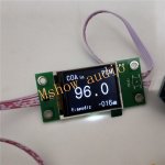
Once I decide on how I'm going to implement this project, proper enclosure, layout, display options and proper cabling decisions will be made.
Ummm, Gee, I don't know. Are you one of those people that puts looks above sound quality? If so, you are not alone.
If great sound quality, and I do mean great, not merely good, great is an option for not too much money starting with the board you have now. But, if you decide on a case and so forth before deciding on sound quality, you almost certainly will end up painting yourself into a corner, so to speak.
Some of what you might want to do could take up more space than you might allow for now. Not necessarily a whole lot more, but not hard for it to be enough not to fit in a cute little case.
I haven't decided on a final case for my dac like that yet, but I do have a test setup which takes up more space than what you have. I have a bigger and better quality +-15v power supply and also a very clean and stable +5v supply. Then I have the dac board, the sample rate converter, a small headphone amp board (which is strongly recommended), and an Arduino (instead of an RPi).
Don't know if you just came across this thread, or if you have been reading for awhile, but it looks more like you just joined recently. If pretty new to this and you don't already know, it is possible to take the cheap dac board you have there (which to me in its current state is utter garbage and I would throw it away if I couldn't make it sound better), and it is possible for mostly some labor and a little bit of money (that sample rate converter is the single most expensive thing) to make it sound like a good $1,000 to maybe $1,400 dac (if comparing to Chinese boards in that price range) in terms of sound quality. It can sound stunningly gorgeous at its very best, or utter garbage as it is now. Please let me also say I am not prone to exaggeration or to normally speak in superlatives. It can be very, very good. Not as good as the best $1,800 dac you could buy, but just a little notch or two below that.
If you want more or less the same sound quality as the DIY above (don't quite know if a little better or not) and you want to use RPi, and you are wiling to accept master mode operation, then you could wait a bit for Allo Katana dac to be ready. Pricing is at about $250 for the basic dac, last I knew.
By the way, the reason for using the sample rate converter and that particular one is to convert all audio to 11.2MHz DSD format. The sweet spot for dac chip you have there is that high sample rate DSD. CDs upsampled and converted sound wonderful (with a few more DIY mods, but you will hear a lot of change just with the SRC).
Last edited:
Working on the through hole component project dac modding again today. Decide to try a dedicated LT1763 regulator for the clock and maybe VCCA. Will try just the clock first then Clock + VCCA on one regulator. The main reason is to get it off the general purpose 3.3v rail which has the MCU and dac digital functions power noise on it (since the power filters on the board do not fully reduce all audible effects of power supply coupled noise). Also, an LT1763 can provide better regulation than the clock is getting now.
In addition, depending on how testing comes out it could be the dac board will end up with two dedicated regulators, one for the clock and a separate one for VCCA. We'll see.
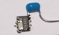
To make it easier to fit the LT1763 in a small space on the bottom of the ground plane reasonably near the clock, I assembled most of the components in advance of soldering the chip to the ground plane. The picture below shows three pins have been left down so they can be soldered to the ground plane. The other pins have been bent up to make the other circuit connections. Attached to two of the pins in an SMD .01uf C0G noise reduction cap, and to two other pins a through hole leaded 1uf X7R for input decoupling (in honor of the through hole component theme). To be attached later will be an SMD 10uf X7R output filter cap.
In addition, depending on how testing comes out it could be the dac board will end up with two dedicated regulators, one for the clock and a separate one for VCCA. We'll see.
To make it easier to fit the LT1763 in a small space on the bottom of the ground plane reasonably near the clock, I assembled most of the components in advance of soldering the chip to the ground plane. The picture below shows three pins have been left down so they can be soldered to the ground plane. The other pins have been bent up to make the other circuit connections. Attached to two of the pins in an SMD .01uf C0G noise reduction cap, and to two other pins a through hole leaded 1uf X7R for input decoupling (in honor of the through hole component theme). To be attached later will be an SMD 10uf X7R output filter cap.
Attachments
Last edited:
Something new to report. Got the clock on it's own regulator, so good there. But, the next thing may be important, not sure yet.
Decided to do an experiment with the LTC6655 reference for AVCC. Put the other three spare 10uf film caps in parallel with the 10uf electrolytic in front of the AVCC opamps. Think I am getting more sound improvement. As I recall, the 47uf AVCC caps at the outputs of the AVCC opamps can be as small as 10uf if using LME49720. Think I will remove all the electrolytics filtering AVCC which is the 10uf before the opamps and the 47uf after. Will replace all of them with my spare 10uf film caps. Think this may be another significant finding to add to the list of what we know. Therefore, anyone building an AVCC supply might want to hold off until I see where this goes.
Decided to do an experiment with the LTC6655 reference for AVCC. Put the other three spare 10uf film caps in parallel with the 10uf electrolytic in front of the AVCC opamps. Think I am getting more sound improvement. As I recall, the 47uf AVCC caps at the outputs of the AVCC opamps can be as small as 10uf if using LME49720. Think I will remove all the electrolytics filtering AVCC which is the 10uf before the opamps and the 47uf after. Will replace all of them with my spare 10uf film caps. Think this may be another significant finding to add to the list of what we know. Therefore, anyone building an AVCC supply might want to hold off until I see where this goes.
Didn't edit my last post soon enough to add a few additional thoughts:
Thinking about it some more, using film caps for AVCC filtering might reasonably be expected to provide some improvement in sound quality. The caps in question are effectively the only electrolytics in the signal path, since AVCC affects the analog output of the dac just as much as does the digital music data being converted to analog. The two signals are effectively multiplied together, which should be fine so long as AVCC is pure DC only (which it is not to the extent noise is present).
Anyway, I just ordered some more Wima film caps in 10uf, 22uf, and 33uf. They will probably be here before the end of the week. Then we will see.
Hey Mark, thanks for your reply. My electronic experience is minimal. I built 6 Drip Electronic pre amp kits for my recording studio a few years ago. They went really well but it was just soldering by numbers. Had anything gone wrong with the build I would have been in trouble as my knowledge is literally zilch.
I guess my goal would be to build a great sounding dac by tapping in to the knowledge here without getting on anyone's nerves and hopefully making some friends. I could only give some laughs in return!!
I'm still reading through this thread which is very long. I think I'll just keep reading for a while and maybe start with trying to understand your AVCC mod.
Last edited:
Hey Alex,
Sounds like you might be trying to take on a pretty big challenge based on what you say about yourself. How did the preamp kits come out, how was the mechanical quality of your work? Do you have a temperature controlled iron with at least a few different sized tips? Different diameter sizes of 60/40 or 63/37 rosin core solder? Small hand tools? Helping hand type of soldering aid? Solder removal braided wick? Do you know how to use a multi-meter, or even have one? Do you have a +-15 volt linear power supply? I hesitate to ask, but do you have any kind of oscilloscope or have you ever played around with one?
I have written about some of the above issues here and there in the thread. Probably some links to posts in that list posted recently.
Also, might you possibly know anyone near where you are who knows more about electronics than you who you could talk to or ask for advice, or maybe have take a look at your project if troubleshooting becomes necessary?
I'm thinking we can try to help you as much as we can remotely, but there are obviously limits to what can be done that way.
Of course, we are only talking about potentially losing a $39 dac board and maybe a few other parts. A lot of work might go down the drain with it, however, but we have had a few people that ran into trouble and recovered from it. Mikett blew up his dac chip somehow, and moved on with an ES9038PRO board he is still optimizing. I blew up all my SMD opamps by accidentally connecting the power backwards. I had to unsolder them all and remove all the components soldered onto the opamps. Took me a couple of days to fix it. So, I guess nothing worse will probably happen to you.
Anyway, I'll be waiting for you to ask specific questions when you are ready.
Yeah it probably is a huge undertaking. The pre-amps went very well and my workmanship is very good. I took my time to make sure I got it right first time, mostly for the above reasons of not being able to fix problems, but generally, I'm OK like that. Like I said though, they were kits so 'Measure twice cut once' was the only policy needed.
I'm thinking I might just upgrade with the Diyaudio amp kit which looks pretty good, just to get myself started, and maybe pick up a cheap (ish) but better dac than the one in my TV which is doing the work at the moment.While I'm doing that, I can follow you guys and try to learn as much as I can without being too obtrusive. You've also assumed right as I will have to pick up a lot more equipment and tools as I go along. I have a few bits but not what is needed for this.
This is a long term project for me so I'm in no rush. I'm also hyper aware that you guys can't baby sit me through it either so dont worry, I won't be expecting g that 😊
You've been extremely helpful already with your advice aleady and I appreciate it very much. I haven't done this much reading since the Brexit referendum 😂😂😂
Through hole component project I2C mod picture available below. Yellow is SCL, Orange is SDA, and Green is ground. This time we are doing it occip style (I am anyway) which does not involve any pin lifting. Only need to tack on three wires and that's it, we're done.
The reason we can get away without any pin lifting this time is because monitoring of MCU firmware shows it does not access any of the registers we are interested in using. Might not always be the case with other dacs in the future, so some practice with pin lifting, unsoldering pins, cutting traces, tacking on wires, etc., may still be worthwhile in order to develop some skill.
This completes enough mods so that I can swap out the old 1st dac board I modded from the test setup and install this one. That means I can look at harmonic distortion compensation for the new board and start doing listening comparisons.
Also, sometime later in the week some more quantity and bigger value film caps should arrive to see if any more practical improvement can be made with AVCC in terms of how it affects sound quality. Don't what will happen, if anything, but probably worth a try.
Attachments
Last edited:
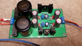
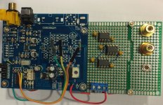
My prototype board
Hello Mark
Time is running and I'm waiting for my components from China.
Now I'm building my prototype with unmoded modules. Then I make the sound compare to my HUD-2. This week I have perhabs time to work an the schematics and update the BOM.
Hello Mark
Time is running and I'm waiting for my components from China.
Now I'm building my prototype with unmoded modules. Then I make the sound compare to my HUD-2. This week I have perhabs time to work an the schematics and update the BOM.
Attachments
Ummm, Gee, I don't know. Are you one of those people that puts looks above sound quality? If so, you are not alone.
If great sound quality, and I do mean great, not merely good, great is an option for not too much money starting with the board you have now. But, if you decide on a case and so forth before deciding on sound quality, you almost certainly will end up painting yourself into a corner, so to speak.
Some of what you might want to do could take up more space than you might allow for now. Not necessarily a whole lot more, but not hard for it to be enough not to fit in a cute little case.
I haven't decided on a final case for my dac like that yet, but I do have a test setup which takes up more space than what you have. I have a bigger and better quality +-15v power supply and also a very clean and stable +5v supply. Then I have the dac board, the sample rate converter, a small headphone amp board (which is strongly recommended), and an Arduino (instead of an RPi).
Don't know if you just came across this thread, or if you have been reading for awhile, but it looks more like you just joined recently. If pretty new to this and you don't already know, it is possible to take the cheap dac board you have there (which to me in its current state is utter garbage and I would throw it away if I couldn't make it sound better), and it is possible for mostly some labor and a little bit of money (that sample rate converter is the single most expensive thing) to make it sound like a good $1,000 to maybe $1,400 dac (if comparing to Chinese boards in that price range) in terms of sound quality. It can sound stunningly gorgeous at its very best, or utter garbage as it is now. Please let me also say I am not prone to exaggeration or to normally speak in superlatives. It can be very, very good. Not as good as the best $1,800 dac you could buy, but just a little notch or two below that.
If you want more or less the same sound quality as the DIY above (don't quite know if a little better or not) and you want to use RPi, and you are wiling to accept master mode operation, then you could wait a bit for Allo Katana dac to be ready. Pricing is at about $250 for the basic dac, last I knew.
By the way, the reason for using the sample rate converter and that particular one is to convert all audio to 11.2MHz DSD format. The sweet spot for dac chip you have there is that high sample rate DSD. CDs upsampled and converted sound wonderful (with a few more DIY mods, but you will hear a lot of change just with the SRC).
Hi Mark,
Your post prompted a bit more reading and research on SRCs. Are they sometimes refereed to as 'reclockers'? I certainly have heard of DSD, but was unaware that all digital audio 'should be' up-sampled to get the best results in audio(DAC) performance. I guess the source is no longer bit-perfect? I will say my DACs are not the weakest link in my modest audio setup - even with the addition of an SRC. As such, I may not fully realize the audible gains you suggest. But I'm certainly willing to try. Hope I do! Furthermore, my 66 yr old ears simply do not capture and discriminate as well as they did years ago. So, sometimes 'real good' sounding is good enough. There is a point of diminishing audible returns for the investments in gear. But I really don't want to debate that point. That's a rabbit hole I avoid as much as I can, especially on forums. In general, most people are too entrenched about what they want to believe. And no, I don't own any $200 IEC power cords!
Having said that, I did not mean to leave you with the impression that my bench setup as illustrated in my pictures, would be the ultimate end result. Like I said, this was the first time, I had actually tried to get the raw I2S data from a RPi and feed it into a DAC board. However limited that DAC board may be. Sure, I have played with lots of DAC hats, but they are largely plug-n-play. So when it simply worked (thanks to ropieee/roon software) I was amazed and surprised. Can it all be made better? No doubt? Will it matter? Possibly.
This MAY be part of a bigger project that I've been rolling around in my head for a couple of years now. But that will be a longer term reality simply due to time constraints. I don't have the luxury of being 'retired' yet.
No offense. I'm glad for you. But now you have provided additional information to consider that - for little money - should yield positive sonic results. I will certainly, seriously consider the SRCs link you provided and will likely order the one that includes SPDIF as well. Why not? BTW, funny you should mention the Katana. Just a couple of weeks ago I was researching the latest RPi DAC hats and came across the Katana from allo. However, their web-page has pulled the offering indicating a newer, more improved Katana would be released in the future. How far in the future remains to be seen. Sounds like it's still a work in progress. I do have the allo BOSS, but I suspect your opinion of most of these RPi hats are of limited audio quality? Yes?
So now I have a new quest of SRCs, understanding what they do and their capabilities in the realm of DACs and DSD playback. On another topic, I do know that the RPi GPIO connector does support the I2C protocol, but I have no direct experience with it. So, I may be asking some questions about that, benefits, etc down the road.
I will continue to read and learn.
Regards,
redjr .....
There is a HAT for RPI that is the AK4137 SRC and outputs to your chosen DAC via I2S.....
Raspi-4137 Raspberry Pi Digital Network Player Supports 32bit 384K DSD256 | eBay
There is a HAT for RPI that is the AK4137 SRC and outputs to your chosen DAC via I2S.....
Raspi-4137 Raspberry Pi Digital Network Player Supports 32bit 384K DSD256 | eBay
Hi redjr,
Thank you for your thoughtful reply. Unfortunately, I think I probably came on a bit strong last time with the intent of getting your attention. Sorry, if is was too much.
Anyway, you raise a number of interesting issues that probably a number of the readers of this thread might be interested in. So, please let me take a try at explaining some of it while trying to keep it intuitive. For simplicity sake, I will use 24-bit audio for any examples.
So, yes, we do have bit perfect file storage and transport of digital audio. The audio was not perfectly converted from it's original analog format to digital, but once digital it stays the same until we intentionally change it or try to convert it back to analog.
The 24 bit data in audio files are the the amplitude of samples taken at equal intervals in time. During the A/D process there can be some errors in both amplitude accuracy, and in timing accuracy. Unintended and unwanted variation in the time spacing between samples is called jitter. Sampling at the wrong time is as bad as an error in sampling amplitude, since the amplitude measured may have been the amplitude a little before or after the time we wanted.
After A/D conversion things are fine until we get to a DAC. There are many different kinds of DACs that have different internal workings. Most modern DACs are sigma-delta types which output changes in voltage amplitude between samples, not absolute amplitude. They are not so good for most instrumentation purposes, but they work well with the way humans hear.
When we want to play music the data in a file may be converted to I2S or PCM format (almost the same things, only slight differences) which have a serial data signal and couple of clock signals. At that point those signals are going to soon be converted back to analog and now any new errors in timing are going to cause distortion of some kind or other. Thus a DAC may be turning samples into analog voltages at the wrong times, which still makes distortion just as though it were the wrong amplitude at the right time.
When I2S is created in a USB to I2S device (think Amanero or XMOS) the clock signals might not be perfectly spaced in time, then as they travel over wires to a DAC various noise sources might cause additional timing errors. It means we have some jitter that we don't want and might like to reduce.
A reclocker (to me) is like a FIFO memory, but that stores the data only very briefly, perhaps less than one whole clock period. As the data is taken out of memory and sent on to the DAC, the readout of memory is timed to a new low-jitter clock which has the effect of reducing any timing errors in the I2S signals.
Upsampling and conversion to DSD is something that may or may not make a DAC sound better. Sometimes it does. The act of upsampling can have some effect of reducing jitter. There is a delay and some reclocking, and there could be some other effects that help make the digital audio data more valid within the new sample rate.
The thing about DACs, DSD, and sample rates, is that a particular DAC may not reproduce every sample rate and or data type with equal accuracy. If fact they usually don't, and the distortion numbers often look lower at lower sample rates, and noise may look better if DSD is not used.
This is a area where we can measure what we hear, although we don't routinely try to measure everything that can happen in some types of DACs. The bigger issue may be that the relationship between measured numbers and how humans perceive enjoyable sound may diverge in a way that maybe has not be fully studied. We know with analog audio that higher order harmonics are more objectionable sounding than very low order harmonics. In fact, some people seem to like very small amounts of 2nd or maybe even 3rd harmonic distortion. Unfortunately, we don't know as much about what people do or don't like about DACs relative to some of the distortion and noise mechanisms we can or could measure.
So, what we have in our case here with our DAC board modification project is we are by experimentation finding out what sounds best to use with these ES9038Q2M DACs. Of course, one should always measure as well as listen, and I don't think we have done as much measuring yet as we should. What I have been doing to have some point of reference to help minimize me from getting fooled by brain bias effects is to compare changes made on my project DAC with sound of a well recognized state of the art commercial DAC. The reference DAC is a Benchmark Media DAC-3. Fortunately, the DAC chip in it is very closely related to the DAC chip in the project DAC, so DAC-3 makes a excellent sound quality target to work towards.
What we have found so far is that many things need attention and improvement to get the best sound quality performance out of our project DACs. I don't think they missed anything that needed doing with DAC-3, at least so far as I can tell. And so no surprise we are finding we need to do everything that needs doing to make movement towards trying to approach its very high quality sound. Now, I am sure we are doing some things differently than DAC-3. There are various reasons for that, and I don't know that we have fully optimized everything that we might yet, but we have found that this particular DAC (at least when clocked at 100MHz) does happen to sound best with upsampled 11.2MHz DSD.
Whew! Hope that helps. Don't know what else to say right now, but if there are remaining questions or issues please let me know and I will try to address them.
-Mark
EDIT: Most recent news on Katana is that v1.2 might start shipping as soon as next week. We will find out more pretty soon, I think.
Also, my 66 year old ears are not as good as they used to be either. However, I can still hear distortion just fine in the frequency range I can still hear, and if the volume level is high enough but not too high.
Last edited:
redjr .....
There is a HAT for RPI that is the AK4137 SRC and outputs to your chosen DAC via I2S.....
Raspi-4137 Raspberry Pi Digital Network Player Supports 32bit 384K DSD256 | eBay
Well there goes more money out of my PayPal account!
... Upsampling and conversion to DSD is something that may or may not make a DAC sound better. Sometimes it does. ...
upsampling from PCM192 to DSD256 causes clear and measurable improvement for ES9038Q2M, however, this is not the case for ES9028PRO. PCM is as good as DSD for PRO chip. apparently, there is some kind of PCM conversion done internally. so, I would say hardware/software upsampling is required for mobile chips. reclocking is another matter though.
- Home
- Source & Line
- Digital Line Level
- ES9038Q2M Board